

DPF零信任(DPF-ZT)参考部署指南
创建于2025年9月8日,更新于2026年5月15日(v26.4 GA)。本参考部署指南(RDG)提供了在零信任模式下,于高性能裸金属基础设施上部署NVIDIA DOCA平台框架(DPF)的全面说明。
文档目录
范围
本参考部署指南(RDG)提供了在零信任模式下,于高性能裸金属基础设施上部署NVIDIA DOCA平台框架(DPF)的全面说明。重点介绍在NVIDIA® BlueField®-3 DPU上设置和使用基于DPU的服务,以提供安全、隔离且硬件加速的环境。
本指南面向构建高度安全裸金属环境(使用NVIDIA BlueField DPU实现加速、隔离和基础设施卸载)的经验丰富的系统管理员、系统工程师和解决方案架构师。
警告
- 本参考实现,顾名思义,是一个特定的、有倾向性的部署示例,旨在解决上述用例。
- 尽管可能存在其他实现类似解决方案的方法,但本文档提供了此特定方法的详细指南。
缩写和首字母缩略词
| 术语 | 定义 | 术语 | 定义 |
|---|---|---|---|
| BFB | BlueField Bootstream | NGC | NVIDIA GPU Cloud |
| DOCA | Data Center Infrastructure-on-a-Chip Architecture | NFS | Network File System |
| DPF | DOCA Platform Framework | OOB | Out-of-Band |
| DPU | Data Processing Unit | PF | Physical Function |
| K8S | Kubernetes | RDG | Reference Deployment Guide |
| KVM | Kernel-based Virtual Machine | RDMA | Remote Direct Memory Access |
| MAAS | Metal as a Service | RoCE | RDMA over Converged Ethernet |
| MTU | Maximum Transmission Unit | ZT | Zero Trust |
引言
NVIDIA BlueField-3数据处理单元(DPU) 是一个400 Gb/s的基础设施计算平台,专为软件定义的网络、存储和网络安全工作负载的线速处理而设计。它结合了强大的计算资源、高速网络和高级可编程性,为现代数据中心提供硬件加速的软件定义解决方案。
NVIDIA DOCA 充分发挥BlueField平台的潜力,支持快速开发能够卸载、加速和隔离数据中心工作负载的应用程序和服务。
然而,部署和管理DPU(尤其是大规模部署)带来了操作挑战。如果没有强大的配置和编排系统,生命周期管理、服务部署和服务功能链(SFC)的网络配置等任务很快就会变得复杂且容易出错。这就是DOCA平台框架(DPF) 发挥作用的地方。
DPF 自动化了DPU的完整生命周期,并简化了高级网络配置。借助DPF,可以无缝部署服务,实现通过DPU数据平面的高效卸载和智能路由。
通过利用DPF,用户可以在裸金属、虚拟机和Kubernetes客户环境中扩展和自动化DPU管理,从而优化性能并简化操作。
DPF支持多种部署模型。本指南重点介绍零信任裸金属部署模型。在此场景中:
- DPU通过其基板管理控制器(BMC) 进行管理
- 所有管理流量均通过DPU的带外(OOB) 网络传输
- 主机被视为数据中心网络的不可信实体。DPU充当主机和网络之间的屏障。
- 主机将DPU视为标准网卡,无法访问内部DPU管理平面**(零信任模式)**
本参考部署指南(RDG) 提供了在零信任模式下安装DPF的逐步示例。它还包括使用标准RDMA和TCP工作负载验证的性能优化实践演示。
作为参考实现的一部分,使用了DPF范围之外的开源组件(例如MAAS、pfSense、Kubespray)来模拟真实的客户部署环境。本指南包括完整的端到端部署过程,包括:
- 基础设施配置
- DPF部署
- DPU配置(redfish)
- 服务配置和部署
- 服务链
参考文献
- NVIDIA BlueField DPU
- NVIDIA DOCA
- NVIDIA DPF Release Notes
- NVIDIA DPF GitHub Repository
- NVIDIA DPF System Overview
- NVIDIA Ethernet Switching
- NVIDIA Cumulus Linux
- What is K8s?
- Kubespray
解决方案架构
关键组件和技术
-
NVIDIA BlueField®数据处理单元(DPU) NVIDIA® BlueField®数据处理单元(DPU)为现代数据中心和超级计算集群带来了前所未有的创新。凭借其强大的计算能力和集成的软件定义硬件加速器(用于网络、存储和安全),BlueField为任何环境中的任何工作负载创建了安全且加速的基础设施,开启了加速计算和AI的新时代。
-
NVIDIA DOCA软件框架 NVIDIA DOCA™释放了NVIDIA® BlueField®网络平台的潜力。通过利用BlueField DPU和SuperNIC的强大功能,DOCA支持快速创建能够卸载、加速和隔离数据中心工作负载的应用程序和服务。它使开发人员能够创建软件定义的、云原生的、DPU和SuperNIC加速的服务,并具有零信任保护,满足现代数据中心的性能和安全需求。
-
NVIDIA ConnectX智能网卡 10/25/40/50/100/200和400G以太网网卡 业界领先的NVIDIA® ConnectX®系列智能网卡提供高级硬件卸载和加速。 NVIDIA以太网网卡为超大规模、公有云和私有云、存储、机器学习、AI、大数据和电信平台提供最高的ROI和最低的总拥有成本。
-
NVIDIA LinkX线缆 NVIDIA® LinkX®线缆和收发器产品系列提供了业界最完整的10、25、40、50、100、200和400GbE以太网以及100、200和400Gb/s
InfiniBand products for Cloud, HPC, hyperscale, Enterprise, telco, storage and artificial intelligence, data center applications.
-
NVIDIA Spectrum 以太网交换机 Flexible form-factors with 16 to 128 physical ports, supporting 1GbE through 400GbE speeds. Based on a ground-breaking silicon technology optimized for performance and scalability, NVIDIA Spectrum switches are ideal for building high-performance, cost-effective, and efficient Cloud Data Center Networks, Ethernet Storage Fabric, and Deep Learning Interconnects. NVIDIA combines the benefits of NVIDIA Spectrum™ switches, based on an industry-leading application-specific integrated circuit (ASIC) technology, with a wide variety of modern network operating system choices, including NVIDIA Cumulus® Linux, SONiC and NVIDIA Onyx®.
-
NVIDIA Cumulus Linux NVIDIA® Cumulus® Linux is the industry's most innovative open network operating system that allows you to automate, customize, and scale your data center network like no other.
-
Kubernetes Kubernetes is an open-source container orchestration platform for deployment automation, scaling, and management of containerized applications.
-
Kubespray Kubespray is a composition of Ansible playbooks, inventory, provisioning tools, and domain knowledge for generic OS/Kubernetes clusters configuration management tasks and provides:
- A highly available cluster
- Composable attributes
- Support for most popular Linux distributions
Solution Design
Solution Logical Design
The logical design includes the following components:
- 1 x Hypervisor node (KVM-based) with ConnectX-7:
- 1 x Firewall VM
- 1 x Jump Node VM
- 1 x MaaS VM
- 3 x K8s Master VMs running all K8s management components
- 4 x Worker nodes (PCI Gen5), each with a 1 x BlueField-3 NIC
- Single High-Speed (HS) switch
- 1 Gb Host Management network

Firewall Design
The pfSense firewall in this solution serves a dual purpose:
- Firewall—provides an isolated environment for the DPF system, ensuring secure operations
- Router—enables Internet access for the management network
Port-forwarding rules for SSH and RDP are configured on the firewall to route traffic to the jump node's IP address in the host management network. From the jump node, administrators can manage and access various devices in the setup, as well as handle the deployment of the Kubernetes (K8s) cluster and DPF components.
The following diagram illustrates the firewall design used in this solution:

Software Stack Components

Error: Make sure to use the exact same versions for the software stack as described above.
Bill of Materials

Deployment and Configuration
Node and Switch Definitions
These are the definitions and parameters used for deploying the demonstrated fabric:
| 交换机 Ports Usage | ||
|---|---|---|
| Hostname | Rack ID | Ports |
mgmt-switch | 1 | swp1-5 |
hs-switch | 1 | swp1-9 |
| Hosts | |||||
|---|---|---|---|---|---|
| Rack | Server Type | Server Name | Switch Port | IP and NICs | Default Gateway |
| Rack1 | Hypervisor Node | hypervisor | mgmt-switch: swp1 | ||
hs-switch: swp1 | lab-br (interface eno1): Trusted LAN IP | ||||
| mgmt-br (interface eno2): - | |||||
| hs-br (interface enp1s0): - | Trusted LAN GW | ||||
| Rack1 | Firewall (Virtual) | fw | - | WAN (lab-br): Trusted LAN IP | |
| LAN (mgmt-br): 10.0.110.254/24 | |||||
| ** OPT1(hs-br):** 172.169.50.1/30 | Trusted LAN GW | ||||
| Rack1 | Jump Node (Virtual) | jump | - |
| 机架 | 节点 | 主机名 | 交换机端口 | IP地址 | 网关 |
|---|---|---|---|---|---|
| Rack1 | Firewall (Virtual) | firewall | - | enp1s0: 10.0.110.253/24 | 10.0.110.254 |
| Rack1 | Jump (Virtual) | jump | - | enp1s0: 10.0.110.252/24 | 10.0.110.254 |
| Rack1 | MaaS (Virtual) | maas | - | enp1s0: 10.0.110.252/24 | 10.0.110.254 |
| Rack1 | Master Node (Virtual) | master1 | - | enp1s0: 10.0.110.1/24 | 10.0.110.254 |
| Rack1 | Master Node (Virtual) | master2 | - | enp1s0: 10.0.110.2/24 | 10.0.110.254 |
| Rack1 | Master Node (Virtual) | master3 | - | enp1s0: 10.0.110.3/24 | 10.0.110.254 |
| Rack1 | Worker Node | worker1 | mgmt-switch: swp2(DPU BMC/OOB) hs-switch: swp2-swp3 | dpubmc: 10.0.110.201/24 dpuoob: 10.0.110.211/24 ens1f0np0/ens1f1np1: 10.0.120.0/22 | 10.0.110.254 |
| Rack1 | Worker Node | worker2 | mgmt-switch: swp3(DPU BMC/OOB) hs-switch: swp4-swp5 | dpubmc: 10.0.110.202/24 dpuoob: 10.0.110.212/24 ens1f0np0/ens1f1np1: 10.0.120.0/22 | 10.0.110.254 |
| Rack1 | Worker Node | worker3 | mgmt-switch: swp4(DPU BMC/OOB) hs-switch: swp6-swp7 | dpubmc: 10.0.110.203/24 dpuoob: 10.0.110.213/24 ens1f0np0/ens1f1np1: 10.0.120.0/22 | 10.0.110.254 |
| Rack1 | Worker Node | worker4 | mgmt-switch: swp5(DPU BMC/OOB) hs-switch: swp8-swp9 | dpubmc: 10.0.110.204/24 dpuoob: 10.0.110.214/24 ens1f0np0/ens1f1np1: 10.0.120.0/22 | 10.0.110.254 |
布线
Hypervisor 节点

裸金属工作节点

网络结构配置
更新 Cumulus Linux
作为最佳实践,请确保使用最新发布的 Cumulus Linux NOS 版本。
有关如何升级 Cumulus Linux 的信息,请参阅 Cumulus Linux 用户指南。
配置 Cumulus Linux 交换机
SN3700 交换机(hs-switch)配置如下:
SN3700 交换机控制台
nv set bridge domain br_hs untagged 1
nv set interface swp1-5 bridge domain br_hs
nv set interface swp1-5 link state up
nv set interface swp1-5 type swp
nv config apply -y
nv config save
SN2201 交换机(mgmt-switch)配置如下:
SN2201 交换机控制台
nv set interface swp1-3 link state up
nv set interface swp1-3 type swp
nv set interface swp1-3 bridge domain br_default
nv set bridge domain br_default untagged 1
nv config apply -y
nv config save
主机配置
注意: 确保工作节点服务器的 BIOS 设置中已启用 SR-IOV,并且服务器已调整为最大性能。
所有工作节点必须具有相同的 BlueField-3 网卡 PCIe 位置,并且必须显示相同的接口名称。
确保您拥有 DPU BMC 和 OOB MAC 地址。
虚拟机管理程序安装和配置
本参考部署指南(RDG)中使用的虚拟机管理程序基于 Ubuntu 24.04 和 KVM。
虽然本文档不详细说明 KVM 安装过程,但需要注意的是,部署防火墙、Jump 和 MaaS 虚拟机(VM)需要以下 ISO:
- Ubuntu 24.04
- pfSense-CE-2.7.2
要实现该解决方案,必须在虚拟机管理程序上创建三个 Linux 网桥:
警告: 确保在受信任的 LAN 中为
lab-br网桥接口配置 DHCP 记录,以分配 IP 地址。
lab-br– 将防火墙 VM 连接到受信任的 LAN。mgmt-br– 将各个 VM 连接到主机管理网络。hs-br– 将防火墙 VM 连接到高速网络。
此外,必须在管理和高速网桥上配置 MTU 为 9000。
(mgmt-br和hs-br)及其上行接口,以确保最佳性能。
Hypervisor netplan配置
network:
    ethernets:
        eno1:
            dhcp4: false
        eno2:
            dhcp4: false
            mtu: 9000
        ens2f0np0:
            dhcp4: false
            mtu: 9000
    bridges:
      lab-br:
         interfaces: [eno1]
         dhcp4: true
      mgmt-br:
         interfaces: [eno2]
         dhcp4: false
         mtu: 9000
      hs-br:
         interfaces: [ens2f0np0]
         dhcp4: false
         mtu: 9000
    version: 2
应用配置:
Hypervisor Console
$ sudo netplan apply
准备基础设施服务器
防火墙VM - pfSense安装与接口配置
从hypervisor下载pfSense CE(社区版)ISO,并进行软件安装。
建议规格:
- vCPU:2
- RAM:2GB
- 存储:10GB
- 网络接口
- 连接到
lab-br的桥接设备 - 连接到
mgmt-br的桥接设备 - 连接到
hs-br的桥接设备
- 连接到
防火墙VM必须连接到hypervisor上的所有三个Linux桥接。在开始安装之前,请确保配置了三个类型为**"Bridge device"**的虚拟网络接口。每个接口应连接到不同的桥接(lab-br、mgmt-br和hs-br),如下图所示。
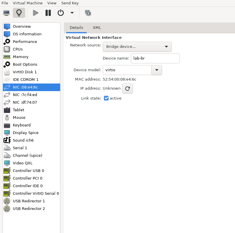
安装完成后,设置向导会显示一个包含多个选项的菜单,例如"Assign Interfaces"和"Reboot System"。在此阶段,您必须为防火墙VM配置网络接口。
- 选择选项2:"Set interface(s) IP address",并按如下方式配置接口:
- WAN (lab-br) – 受信任的LAN IP(静态/DHCP)
- LAN (mgmt-br) – 静态IP
10.0.110.254/24 - OPT1 (hs-br) – 静态IP
10.0.123.254/22
- 接口配置完成后,使用主机管理网络中的Web浏览器访问防火墙Web界面,完成配置。
接下来,安装Jump VM。该VM用作运行浏览器的平台,用于访问防火墙的Web界面(UI)以进行安装后配置。
Jump VM
建议规格:
- vCPU:4
- RAM:8GB
- 存储:100GB
- 网络接口:桥接设备,连接到
mgmt-br
步骤:
-
进行标准的Ubuntu 24.04安装。在此设置中的所有主机上使用以下登录凭据:
用户名 密码 depuser user -
通过创建以下Netplan配置启用互联网连接和DNS解析:
注意:在MaaS VM安装并配置之前,使用
10.0.110.254作为临时DNS名称服务器。完成MaaS安装后,更新Netplan文件,将此地址替换为MaaS IP:10.0.110.252。Jump Node netplan
network: ethernets: enp1s0: dhcp4: false addresses: [10.0.110.253/24] nameservers: search: [dpf.rdg.local.domain] addresses: [10.0.110.254] routes: - to: default via: 10.0.110.254 version: 2 -
应用配置:
Jump Node Console
depuser@jump:~$ sudo netplan apply -
更新和升级系统:
Jump Node Console
depuser@jump:~$ sudo apt update -y depuser@jump:~$ sudo apt upgrade -y -
安装并配置Xfce桌面环境和XRDP(RDP的补充包):
Jump Node Console
depuser@jump:~$ sudo apt install -y xfce4 xfce4-goodies depuser@jump:~$ sudo apt install -y lightdm-gtk-greeter depuser@jump:~$ sudo apt install -y xrdp depuser@jump:~$ echo "xfce4-session" | tee .xsession depuser@jump:~$ sudo systemctl restart xrdp -
安装并配置Xfce桌面环境和TigerVNC(VNC远程访问):
-
安装所需包:
Jump Node Console
depuser@jump:~$ sudo apt-get update depuser@jump:~$ sudo apt-get -y install tigervnc-standalone-server tigervnc-scraping-server tigervnc-tools xfce4 xfce4-goodies dbus-x11 -
将Xfce设置为X会话,并为depuser创建VNC密码:
Jump Node Console
depuser@jump:~$ echo "xfce4-session" | tee ~/.xsession depuser@jump:~$ chmod +x ~/.xsession depuser@jump:~$ vncpasswd -
将VNC显示
:1映射到depuser(systemd模板单元读取此文件以了解哪个用户绑定到哪个显示):Jump Node Console
depuser@jump:~$ sudo tee /etc/tigervnc/vncserver.users > /dev/null <<'EOF' :1=depuser EOF -
创建systemd模板单元,该单元在每次启动/重启时运行官方的TigerVNC
vncserver包装器(包装器处理PID文件、先前会话清理,并通过-xstartup启动xfce4):Jump Node Console
depuser@jump:~$ sudo tee /etc/systemd/system/vncserver@.service > /dev/null <<'EOF' [Unit] Description=Start TigerVNC server at startup After=syslog.target network.target [Service] Type=forking User=depuser Group=depuser WorkingDirectory=/home/depuser PIDFile=/home/depuser/.vnc/%H%i.pid ExecStartPre=-/usr/bin/vncserver -kill %i > /dev/null 2>&1 || : ExecStart=/usr/bin/vncserver -xstartup /usr/bin/startxfce4 -SecurityTypes VncAuth,TLSVnc -geometry 1920x1080 -localhost no -nolisten tcp %i ExecStop=/usr/bin/vncserver -kill %i > /dev/null 2>&1 || : [Install] WantedBy=multi-user.target EOF -
启用服务并立即启动(显示
:1绑定到TCP端口5901;服务立即启动并在每次后续重启时启动):Jump Node Console
depuser@jump:~$ sudo systemctl daemon-reload depuser@jump:~$ sudo systemctl enable --now vncserver@:1.service depuser@jump:~$ sudo systemctl status vncserver@:1.service -
验证VNC正在监听端口5901:
Jump Node Console
depuser@jump:~$ ss -tlnp | grep 5901 -
使用
vncpasswd设置的密码,将VNC查看器(TigerVNC Viewer、RealVNC、Remmina)连接到<jump-ip>:1。
-
-
安装Firefox以访问防火墙Web界面。
interface:
Jump Node Console
$ sudo apt install -y firefox
-
Install and configure an NFS server with the
/mnt/dpf_sharedirectory:Jump Node Console
sudo apt install -y nfs-server $ sudo mkdir -m 777 /mnt/dpf_share $ sudo vi /etc/exports -
Add the following line to
/etc/exports:Jump Node Console
/mnt/dpf_share 10.0.110.0/24(rw,sync,no_subtree_check) -
Restart the NFS server:
Jump Node Console
$ sudo systemctl restart nfs-server -
Create the directory
bfbunder/mnt/dpf_sharewith the same permissions as the parent directory:Jump Node Console
$ sudo mkdir -m 777 /mnt/dpf_share/bfb -
Generate an SSH key pair for
depuserin the jump node (later on will be imported to the admin user in MaaS to enable password-less login to the provisioned servers):Jump Node Console
depuser@jump:~$ ssh-keygen -t rsa -
Reboot the jump node to display the graphical user interface:
Jump Node Console
depuser@jump:~$ sudo rebootWarning: After setting up port-forwarding rules on the firewall (next steps), remote login to the graphical interface of the Jump node will be available. Concurrent login to the local graphical console and using RDP isn't possible, make sure to first log out from the local console when switching to RDP connection.
Firewall VM – Web Configuration
From your Jump node, open a Firefox web browser and navigate to the pfSense web UI (http://10.0.110.254. The default login credentials are admin/pfsense). The login page should appear as follows:
Warning: The IP addresses from the trusted LAN network under "DNS servers" and "Interfaces - WAN" are blurred.

Proceed with the following configurations:
Warning: The following screenshots display only a part of the configuration view. Make sure to not miss any of the steps mentioned below!
- Interfaces:
- WAN (lab-br) – mark "Enable interface", unmark "Block private networks and loopback addresses"

- LAN (mgmt-br) – mark "Enable interface", "IPv4 configuration type": Static IPv4 ("IPv4 Address": 10.0.110.254/24, "IPv4 Upstream Gateway": None), "MTU": 9000

- OPT1 (hs-br) – mark "Enable interface", "IPv4 configuration type": Static IPv4 ("IPv4 Address": 10.0.123.254/22, "IPv4 Upstream Gateway": None), "MTU": 9000

- Firewall:
-
NAT -> Port Forward -> Add rule -> "Interface": WAN, "Address Family": IPv4, "Protocol": TCP, "Destination": WAN address, "Destination port range": ("From port": SSH, "To port": SSH), "Redirect target IP": ("Type": Address or Alias, "Address": 10.0.110.253), "Redirect target port": SSH, "Description": NAT SSH

-
NAT -> Port Forward -> Add rule -> "Interface": WAN, "Address Family": IPv4, "Protocol": TCP, "Destination": WAN address, "Destination port range": ("From port": VNC, "To port": VNC), "Redirect target IP": ("Type": Address or Alias, "Address": 10.0.110.253), "Redirect target port": NAT VNC, "Description": NAT VNC

-

-
Rules -> OPT1 -> Add rule -> "Action": Pass, "Interface": OPT1, "Address Family": IPv4+IPv6, "Protocol": Any, "Source": Any, "Destination": Any

MaaS VM
Suggested specifications:
- vCPU: 4
- RAM: 4 GB
- Storage: 100 GB
- Network interface: Bridge device, connected to
mgmt-br
Procedure:
-
Perform a regular Ubuntu installation on the MaaS VM.
-
Create the following Netplan configuration to enable internet connectivity and DNS resolution:
Warning: Use
10.0.110.254as a temporary DNS nameserver. After the MaaS installation, replace this with the MaaS IP address (10.0.110.252) in both the Jump and MaaS VM Netplan files.MaaS netplan
network: ethernets: enp1s0: dhcp4: false addresses: [10.0.110.252/24] nameservers: search: [dpf.rdg.local.domain] addresses: [10.0.110.254] routes: - to: default via: 10.0.110.254 version: 2 -
Apply the netplan configuration:
MaaS Console
depuser@maas:~$ sudo netplan apply -
Update and upgrade the system:
MaaS Console
depuser@maas:~$ sudo apt update -y
depuser@maas:~$ sudo apt upgrade -y
安装PostgreSQL并为MaaS配置数据库:
MaaS控制台
$ sudo -i
# apt install -y postgresql
# systemctl disable --now systemd-timesyncd
# export MAAS_DBUSER=maasuser
# export MAAS_DBPASS=maaspass
# export MAAS_DBNAME=maas
# sudo -i -u postgres psql -c "CREATE USER \"$MAAS_DBUSER\" WITH ENCRYPTED PASSWORD '$MAAS_DBPASS'"
# sudo -i -u postgres createdb -O "$MAAS_DBUSER" "$MAAS_DBNAME"
安装MaaS:
MaaS控制台
# snap install maas
初始化MaaS:
MaaS控制台
# maas init region+rack --maas-url http://10.0.110.252:5240/MAAS --database-uri "postgres://$MAAS_DBUSER:$MAAS_DBPASS@localhost/$MAAS_DBNAME"
创建管理员账户:
MaaS控制台
# maas createadmin --username admin --password admin --email admin@example.com
保存管理员API密钥:
MaaS控制台
# maas apikey --username admin > admin-apikey
登录MaaS服务器:
MaaS控制台
# maas login admin http://localhost:5240/MAAS "$(cat admin-apikey)"
配置MaaS(将 <Trusted_LAN_NTP_IP> 和 <Trusted_LAN_DNS_IP> 替换为环境中的IP地址):
MaaS控制台
# maas admin domain update maas name="dpf.rdg.local.domain"
# maas admin maas set-config name=ntp_servers value="<Trusted_LAN_NTP_IP>"
# maas admin maas set-config name=network_discovery value="disabled"
# maas admin maas set-config name=upstream_dns value="<Trusted_LAN_DNS_IP>"
# maas admin maas set-config name=dnssec_validation value="no"
# maas admin maas set-config name=default_osystem value="ubuntu"
定义并配置IP范围和子网:
MaaS控制台
# maas admin ipranges create type=dynamic start_ip="10.0.110.51" end_ip="10.0.110.120"
# maas admin ipranges create type=dynamic start_ip="10.0.110.225" end_ip="10.0.110.240"
# maas admin ipranges create type=reserved start_ip="10.0.110.10" end_ip="10.0.110.10" comment="c-plane VIP"
# maas admin ipranges create type=reserved start_ip="10.0.110.200" end_ip="10.0.110.200" comment="kamaji VIP"
# maas admin ipranges create type=reserved start_ip="10.0.110.251" end_ip="10.0.110.254" comment="dpfmgmt"
# maas admin vlan update 0 untagged dhcp_on=True primary_rack=maas mtu=9000
# maas admin dnsresources create fqdn=kube-vip.dpf.rdg.local.domain ip_addresses=10.0.110.10
# maas admin dnsresources create fqdn=jump.dpf.rdg.local.domain ip_addresses=10.0.110.253
# maas admin dnsresources create fqdn=fw.dpf.rdg.local.domain ip_addresses=10.0.110.254
为所有DPU节点配置静态DHCP租约(将MAC地址替换为工作节点DPU BMC/OOB接口MAC):
MaaS控制台
# maas admin reserved-ips create ip="10.0.110.201" mac_address="58:a2:e1:73:6a:0b" comment="dpu-worker1-bmc"
# maas admin reserved-ips create ip="10.0.110.211" mac_address="58:a2:e1:73:6a:0a" comment="dpu-worker1-oob"
# maas admin reserved-ips create ip="10.0.110.202" mac_address="58:a2:e1:73:6a:7d" comment="dpu-worker2-bmc"
# maas admin reserved-ips create ip="10.0.110.212" mac_address="58:a2:e1:73:6a:7c" comment="dpu-worker2-oob"
# maas admin reserved-ips create ip="10.0.110.203" mac_address="58:a2:e1:73:6a:a7" comment="dpu-worker3-bmc"
# maas admin reserved-ips create ip="10.0.110.213" mac_address="58:a2:e1:73:6a:a6" comment="dpu-worker3-oob"
# maas admin reserved-ips create ip="10.0.110.204" mac_address="58:a2:e1:73:6a:dd" comment="dpu-worker4-bmc"
# maas admin reserved-ips create ip="10.0.110.214" mac_address="58:a2:e1:73:6a:dc" comment="dpu-worker4-oob"
完成MaaS设置:
- 连接到Jump节点GUI,访问MaaS UI:
http://10.0.110.252:5240/MAAS。 - 在首页上,验证“区域名称”和“DNS转发器”,然后继续。
- 在镜像选择页面上,选择 Ubuntu 24.04 LTS (amd64) 并同步镜像。

- 将之前为
depuser生成的SSH密钥(id_rsa.pub)导入MaaS管理员用户配置文件,并完成设置。
将Jump和MaaS VM的Netplan文件中的DNS名称服务器IP地址从10.0.110.254更新为10.0.110.252,然后重新应用配置。
K8s Master VMs
建议规格:
- vCPU:8
- RAM:16GB
- 存储:100GB
- 网络接口:桥接设备,连接到
mgmt-br
-
在使用MaaS配置Kubernetes(K8s)Master VM之前,创建具有空存储的所需虚拟磁盘。使用以下一行命令创建三个100 GB的QCOW2虚拟磁盘:
Hypervisor控制台
$ for i in $(seq 1 3); do qemu-img create -f qcow2 /var/lib/libvirt/images/master$i.qcow2 100G; done此命令在
/var/lib/libvirt/images/目录中生成以下磁盘:master1.qcow2master2.qcow2master3.qcow2
-
在virt-manager中配置VM:
- 打开 virt-manager 并创建三个虚拟机:
- 为每个VM分配相应的虚拟磁盘(
master1.qcow2、master2.qcow2或master3.qcow2)。 - 使用建议的规格(vCPU、RAM、存储和网络接口)配置每个VM。
- 为每个VM分配相应的虚拟磁盘(
- 在VM设置期间,确保在 启动选项 选项卡下选择了 NIC。这确保VM可以PXE启动以进行MaaS配置。
- 配置完成后,关闭所有VM。
- 打开 virt-manager 并创建三个虚拟机:
-
创建并配置VM后,通过MaaS界面进行配置。MaaS将处理操作系统安装和部署过程中的进一步设置。
使用MaaS配置Master VM
安装virsh并设置SSH访问
-
从Jump节点SSH到MaaS VM:
MaaS控制台
depuser@jump:~$ ssh maas depuser@maas:~$ sudo -i -
安装
virsh客户端以与hypervisor通信:MaaS控制台
# apt install -y libvirt-clients -
为
root用户生成SSH密钥并将其复制到libvirtd组中的hypervisor用户:MaaS控制台
# ssh-keygen -t rsa # ssh-copy-id ubuntu@<hypervisor_MGMT_IP> -
验证SSH访问和与hypervisor的
virsh通信:MaaS控制台
# virsh -c qemu+ssh://ubuntu@<hypervisor_MGMT_IP>/system list --all预期输出:
MaaS控制台
Id Name State ------------------------------ 1 fw running 2 jump running 3 maas running - master1 shut off - master2 shut off - master3 shut off -
将SSH密钥复制到所需的MaaS目录(适用于基于snap的安装):
MaaS控制台
#
mkdir -p /var/snap/maas/current/root/.ssh
# cp .ssh/id_rsa* /var/snap/maas/current/root/.ssh/
Get MAC Addresses of the Master VMs
Retrieve the MAC addresses of the Master VMs:
MaaS Console
# for i in $(seq 1 3); do virsh -c qemu+ssh://ubuntu@<hypervisor_MGMT_IP>/system dumpxml master$i | grep 'mac address'; done
Example output:
MaaS Console
<mac address='52:54:00:a9:9c:ef'/>
<mac address='52:54:00:19:6b:4d'/>
<mac address='52:54:00:68:39:7f'/>
Add Master VMs to MaaS
-
Add the Master VMs to MaaS:
Note: Once added, MaaS will automatically start the newly added VMs commissioning (discovery and introspection).
MaaS Console
# maas admin machines create hostname=master1 architecture=amd64/generic mac_addresses='52:54:00:a9:9c:ef' power_type=virsh power_parameters_power_address=qemu+ssh://ubuntu@<hypervisor_MGMT_IP>/system power_parameters_power_id=master1 skip_bmc_config=1 testing_scripts=none Success. Machine-readable output follows: { "description": "", "status_name": "Commissioning", ... "status": 1, ... "system_id": "c3seyq", ... "fqdn": "master1.dpf.rdg.local.domain", "power_type": "virsh", ... "status_message": "Commissioning", "resource_uri": "/MAAS/api/2.0/machines/c3seyq/" } # maas admin machines create hostname=master2 architecture=amd64/generic mac_addresses='52:54:00:19:6b:4d' power_type=virsh power_parameters_power_address=qemu+ssh://ubuntu@<hypervisor_MGMT_IP>/system power_parameters_power_id=master2 skip_bmc_config=1 testing_scripts=none # maas admin machines create hostname=master3 architecture=amd64/generic mac_addresses='52:54:00:68:39:7f' power_type=virsh power_parameters_power_address=qemu+ssh://ubuntu@<hypervisor_MGMT_IP>/system power_parameters_power_id=master3 skip_bmc_config=1 testing_scripts=none -
Repeat the command for
master2andmaster3with their respective MAC addresses. -
Verify commissioning by waiting for the status to change to "Ready" in MaaS.

After commissioning, the next phase is deployment (OS provisioning).
Configure Master VMs Network
To ensure persistence across reboots, assign a static IP address to the management interface of the master nodes.
For each Master VM:
-
Navigate to Network and click "actions" near the management interface (a small arrowhead pointing down), then select "Edit Physical".
- Configure as follows:
-
Subnet: 10.0.110.0/24
-
IP Mode: Static Assign
-
Address: Assign
10.0.110.1formaster1,10.0.110.2formaster2, and10.0.110.3formaster3.
-
- Configure as follows:
-
Save the interface settings for each VM.
Deploy Master VMs Using Cloud-Init
-
Use the following cloud-init script to configure the necessary software and ensure persistency:
Master nodes cloud-init
#cloud-config system_info: default_user: name: depuser passwd: "$6$jOKPZPHD9XbG72lJ$evCabLvy1GEZ5OR1Rrece3NhWpZ2CnS0E3fu5P1VcZgcRO37e4es9gmriyh14b8Jx8gmGwHAJxs3ZEjB0s0kn/" lock_passwd: false groups: [adm, audio, cdrom, dialout, dip, floppy, lxd, netdev, plugdev, sudo, video] sudo: ["ALL=(ALL) NOPASSWD:ALL"] shell: /bin/bash ssh_pwauth: True package_upgrade: true runcmd: - apt-get update - apt-get -y install nfs-common -
Deploy the master VMs:
-
Select all three Master VMs → Actions → Deploy.
-
Toggle Cloud-init user-data and paste the cloud-init script.
-
Start the deployment and wait for the status to change to "Ubuntu 24.04 LTS".


-
Verify Deployment
-
SSH into the Master VMs from the Jump node:
Jump Node Console
depuser@jump:~$ ssh master1 depuser@master1:~$ -
Run
sudowithout a password:Master1 Console
depuser@master1:~$ sudo -i root@master1:~# -
Verify installed packages:
Master1 Console
root@master1:~# apt list --installed | egrep 'nfs-common' nfs-common/noble,now 1:2.6.4-3ubuntu5 amd64 [installed] -
Reboot the Master VMs to complete the provisioning.
Master1 Console
root@master1:~# reboot
Repeat the verification commands for master2 and master3.
K8s Cluster Deployment and Configuration
Kubespray Deployment and Configuration
In this solution, the Kubernetes (K8s) cluster is deployed using a modified Kubespray (based on release v2.28.1) with a non-root depuser account from the Jump Node. The modifications in Kubespray are designed to meet the DPF prerequisites as described in the User Manual and facilitate cluster deployment and scaling.
-
Download the modified Kubespray archive: Unknown Attachment.
-
Extract the contents and navigate to the extracted directory:
Jump Node Console
$ tar -xzf /home/depuser/modified_kubespray_v2.28.1.tar.gz $ cd kubespray/ depuser@jump:~/kubespray$ -
Set the K8s API VIP address and DNS record. Replace it with your own IP address and DNS record if different:
Jump Node Console
depuser@jump:~/kubespray$ sed -i '/# kube_vip_address:/s/.*/kube_vip_address: 10.0.110.10/' inventory/mycluster/group_vars/k8s_cluster/addons.yml depuser@jump:~/kubespray$ sed -i '/apiserver_loadbalancer_domain_name:/s/.*/apiserver_loadbalancer_domain_name: "kube-vip.dpf.rdg.local.domain"/' roles/kubespray_defaults/defaults/main/main.yml -
Install the necessary dependencies and set up the Python virtual environment:
Jump Node Console
depuser@jump:~/kubespray$ sudo apt -y install python3-pip jq python3.12-venv depuser@jump:~/kubespray$ python3 -m venv .venv depuser@jump:~/kubespray$ source .venv/bin/activate (.venv) depuser@jump:~/kubespray$ python3 -m pip install --upgrade pip (.venv) depuser@jump:~/kubespray$ pip install -U -r requirements.txt (.venv) depuser@jump:~/kubespray$ pip install ruamel-yaml -
Verify that the
kube_network_pluginis set toflanneland thatkube_proxy_removeis set tofalsein theinventory/mycluster/group_vars/k8s_cluster/k8s-cluster.ymlfile.
inventory/mycluster/group_vars/k8s_cluster/k8s-cluster.yml
[depuser@jump kubespray-2.28.0]$ vim inventory/mycluster/group_vars/k8s_cluster/k8s-cluster.yml
.....
## Change this to use another Kubernetes version, e.g. a current beta release
kube_version: 1.32.8
.....
# Choose network plugin (cilium, calico, kube-ovn, weave or flannel. Use cni for generic cni plugin)
# Can also be set to 'cloud', which lets the cloud provider setup appropriate routing
kube_network_plugin: flannel
....
# Kube-proxy proxyMode configuration.
# Can be ipvs, iptables
kube_proxy_remove: false
kube_proxy_mode: ipvs
.....
-
Review and edit the
inventory/mycluster/hosts.yamlfile to define the cluster nodes. The following is the configuration for this deployment:inventory/mycluster/hosts.yaml
all:
  hosts:
    master1:
      ansible_host: 10.0.110.1
      ip: 10.0.110.1
      access_ip: 10.0.110.1
      node_labels:
        "k8s.ovn.org/zone-name": "master1"
    master2:
      ansible_host: 10.0.110.2
      ip: 10.0.110.2
      access_ip: 10.0.110.2
      node_labels:
        "k8s.ovn.org/zone-name": "master2"
    master3:
      ansible_host: 10.0.110.3
      ip: 10.0.110.3
      access_ip: 10.0.110.3
      node_labels:
        "k8s.ovn.org/zone-name": "master3"
  children:
    kube_control_plane:
      hosts:
        master1:
        master2:
        master3:
    kube_node:
      hosts:
    etcd:
      hosts:
        master1:
        master2:
        master3:
    k8s_cluster:
      children:
        kube_control_plane:
Deploying Cluster Using Kubespray Ansible Playbook
-
Run the following command from the Jump Node to initiate the deployment process:
Warning: Ensure you are in the Python virtual environment (
.venv) when running the command.Jump Node Console
(.venv) depuser@jump:~/kubespray$ ansible-playbook -i inventory/mycluster/hosts.yaml --become --become-user=root cluster.yml -
It takes a while for this deployment to complete. Make sure there are no errors. Successful result example:

Success: It is recommended to keep the shell from which Kubespray has been running open, later on it will be useful when performing cluster scale out to add the worker nodes.
K8s Deployment Verification
To simplify managing the K8s cluster from the Jump Host, set up kubectl with bash auto-completion.
-
Copy
kubectland the kubeconfig file frommaster1to the Jump Host:Jump Node Console
## Connect to master1 depuser@jump:~$ ssh master1 depuser@master1:~$ cp /usr/local/bin/kubectl /tmp/ depuser@master1:~$ sudo cp /root/.kube/config /tmp/kube-config depuser@master1:~$ sudo chmod 644 /tmp/kube-config -
In another terminal tab, copy the files to the Jump Host:
Jump Node Console
depuser@jump:~$ scp master1:/tmp/kubectl /tmp/ depuser@jump:~$ sudo chown root:root /tmp/kubectl depuser@jump:~$ sudo mv /tmp/kubectl /usr/local/bin/ depuser@jump:~$ mkdir -p ~/.kube depuser@jump:~$ scp master1:/tmp/kube-config ~/.kube/config depuser@jump:~$ chmod 600 ~/.kube/config -
Enable bash auto-completion for
kubectl:-
Verify if bash-completion is installed:
Jump Node Console
depuser@jump:~$ type _init_completionIf installed, the output includes:
Jump Node Console
_init_completion is a function -
If not installed, install it:
Jump Node Console
depuser@jump:~$ sudo apt install -y bash-completion -
Set up the
kubectlcompletion script:Jump Node Console
depuser@jump:~$ kubectl completion bash | sudo tee /etc/bash_completion.d/kubectl > /dev/null
depuser@jump:~$ bash
-
-
Check the status of the nodes in the cluster:
Jump Node Console
depuser@jump:~$ kubectl get nodesExpected output:
Jump Node Console
NAME STATUS ROLES AGE VERSION master1 Ready control-plane 3m59s v1.32.8 master2 Ready control-plane 3m51s v1.32.8 master3 Ready control-plane 3m48s v1.32.8 -
Check the pods in all namespaces:
Jump Node Console
depuser@jump:~$ kubectl get pods -AExpected output:
Jump Node Console
[depuser@setup5-jump ~]$ kubectl get pods -A
NAMESPACE     NAME                              READY   STATUS    RESTARTS   AGE
kube-system   coredns-5c54f84c97-7245f          1/1     Running   0          3m41s
kube-system   coredns-5c54f84c97-gk4pb          1/1     Running   0          3m38s
kube-system   dns-autoscaler-56cb45595c-bv28g   1/1     Running   0          3m40s
kube-system   kube-apiserver-master1            1/1     Running   0          4m43s
kube-system   kube-apiserver-master2            1/1     Running   0          4m34s
kube-system   kube-apiserver-master3            1/1     Running   0          4m32s
kube-system   kube-controller-manager-master1   1/1     Running   1          4m43s
kube-system   kube-controller-manager-master2   1/1     Running   2          4m34s
kube-system   kube-controller-manager-master3   1/1     Running   1          4m32s
kube-system   kube-flannel-cptzm                1/1     Running   0          3m54s
kube-system   kube-flannel-m2gw4                1/1     Running   0          3m54s
kube-system   kube-flannel-ql46d                1/1     Running   0          3m54s
kube-system   kube-proxy-62dwr                  1/1     Running   0          4m35s
kube-system   kube-proxy-dc4sb                  1/1     Running   0          4m39s
kube-system   kube-proxy-mhbtb                  1/1     Running   0          4m32s
kube-system   kube-scheduler-master1            1/1     Running   1          4m43s
kube-system   kube-scheduler-master2            1/1     Running   1          4m34s
kube-system   kube-scheduler-master3            1/1     Running   1          4m32s
kube-system   kube-vip-master1                  1/1     Running   0          4m43s
kube-system   kube-vip-master2                  1/1     Running   0          4m34s
kube-system   kube-vip-master3                  1/1     Running   0          4m32s
DPF Installation
Software Prerequisites and Required Variables
-
Start by installing the remaining software prerequisites.
Jump Node Console
## Connect to master1 to copy helm client utility that was installed during kubespray deployment $ depuser@jump:~$ ssh master1 depuser@master1:~$ cp /usr/local/bin/helm /tmp/ ## In another tab depuser@jump:~$ scp master1:/tmp/helm /tmp/ depuser@jump:~$ sudo chown root:root /tmp/helm depuser@jump:~$ sudo mv /tmp/helm /usr/local/bin/ ## Verify that envsubst utility is installed depuser@jump:~$ which envsubst /usr/bin/envsubst -
Proceed to clone the doca-platform Git repository:
Jump Node Console
$ git clone https://github.com/NVIDIA/doca-platform.git -
Change directory to doca-platform and checkout to tag v26.4.0:
Jump Node Console
$ cd doca-platform/
$ git checkout v26.4.0
-
切换到 readme.md 目录,所有命令将在此运行:
跳板机控制台
$ cd docs/public/user-guides/zero-trust/use-cases/passthrough/ -
更改 BMC root 密码。 在零信任模式下,配置 DPU 需要通过 Redfish 进行身份验证。 为此,您必须为 DPF 将要管理的所有 DPU 设置相同的 BMC root 密码。有关如何设置 BMC root 密码的更多信息,请参阅 BlueField DPU 管理员快速入门指南。
通过 SSH 连接到第一个 DPU BMC 以更改 BMC root 密码:
跳板机控制台
$ ssh root@10.0.110.201 root@10.0.110.201's password: <BMC Root Password. Default root/0penBmc. need to change first time to $BMC_ROOT_PASSWORD in the manifests/00-env-vars/envvars.env file> -
修改
manifests/00-env-vars/envvars.env中的变量以匹配您的环境,然后 source 该文件:注意:将以下文件中的变量值替换为适合您设置的值。特别注意
DPUCLUSTER_INTERFACE、BMC_ROOT_PASSWORD和DPU's serial number。 要获取DPU's serial number,可以使用以下命令。示例:$ curl -k -u root:'BMC root password' https://10.0.110.201/redfish/v1/Systems/Bluefield | jq -r '.SerialNumber | ascii_downcase' % Total % Received % Xferd Average Speed Time Time Time Current Dload Upload Total Spent Left Speed 100 4970 100 4970 0 0 4211 0 0:00:01 0:00:01 --:--:-- 4211 mt2402xz0f7xmanifests/00-env-vars/envvars.env
## IP Address for the Kubernetes API server of the target cluster on which DPF is installed. ## This should never include a scheme or a port. ## e.g. 10.10.10.10 export TARGETCLUSTER_API_SERVER_HOST=10.0.110.10 ## Port for the Kubernetes API server of the target cluster on which DPF is installed. ## e.g. 6443 export TARGETCLUSTER_API_SERVER_PORT=6443 ## Virtual IP used by the load balancer for the DPU Cluster. Must be a reserved IP from the management subnet and not ## allocated by DHCP. export DPUCLUSTER_VIP=10.0.110.200 ## Interface on which the DPUCluster load balancer will listen. Should be the management interface of the control plane node. export DPUCLUSTER_INTERFACE=ens160 ## IP address to the NFS server used as storage for the BFB. export NFS_SERVER_IP=10.0.110.253 ## The DPF REGISTRY is the Helm repository URL where the DPF Operator Chart resides. ## Usually this is the NVIDIA Helm NGC registry. For development purposes, this can be set to a different repository. export REGISTRY=https://helm.ngc.nvidia.com/nvidia/doca ## The DPF TAG is the version of the DPF components which will be deployed in this guide. export TAG=v26.4.0 ## URL to the BFB used in the `bfb.yaml` and linked by the DPUSet. export BFB_URL="https://nbu-nfs.gtm.nvidia.com/auto/sw_mc_soc_release/doca_dpu/doca_3.4.0/20260428/bfbs/pk/bf-bundle-3.4.0-73_26.04_ubuntu-24.04_64k_prod.bfb" ## IP_RANGE_START and IP_RANGE_END ## These define the IP range for DPU discovery via Redfish/BMC interfaces ## Example: If your DPU have BMC IPs in range 10.0.110.201-240 ## export IP_RANGE_START=10.0.110.201 ## export IP_RANGE_END=10.0.110.204 ## Start of DPUDiscovery IpRange export IP_RANGE_START=10.0.110.201 ## End of DPUDiscovery IpRange export IP_RANGE_END=10.0.110.204 # The password used for DPU BMC root login, must be the same for all DPU # For more information on how to set the BMC root password refer to BlueField DPU Administrator Quick Start Guide. export BMC_ROOT_PASSWORD=<set your BMC_ROOT_PASSWORD> -
导出安装所需的环境变量:
跳板机控制台
$ source manifests/00-env-vars/envvars.env
DPF Operator 安装
验证 rshim 服务
验证 rshim 服务是否正在运行。
-
通过 SSH 连接到第一个 DPU BMC:
跳板机控制台
$ ssh root@10.0.110.201 -
验证
rshim服务是否正在运行,如果未运行则启动它。跳板机控制台
root@dpu-bmc:~# systemctl status rshim * rshim.service - rshim driver for BlueField SoC Loaded: loaded (/usr/lib/systemd/system/rshim.service; enabled; preset: disabled) Active: active (running) since Mon 2025-07-14 13:21:34 UTC; 18h ago Docs: man:rshim(8) Process: 866 ExecStart=/usr/sbin/rshim $OPTIONS (code=exited, status=0/SUCCESS) Main PID: 874 (rshim) CPU: 2h 43min 44.730s CGroup: /system.slice/rshim.service `-874 /usr/sbin/rshim Jul 14 13:21:34 dpu-bmc (rshim)[866]: rshim.service: Referenced but unset environment variable evaluates to an empty string: OPTIONS Jul 14 13:21:34 dpu-bmc rshim[874]: Created PID file: /var/run/rshim.pid Jul 14 13:21:34 dpu-bmc rshim[874]: USB device detected Jul 14 13:21:38 dpu-bmc rshim[874]: Probing usb-2.1 Jul 14 13:21:38 dpu-bmc rshim[874]: create rshim usb-2.1 Jul 14 13:21:39 dpu-bmc rshim[874]: rshim0 attached root@dpu-bmc:~# ls /dev/rshim0 boot console misc rshim # To start the rshim, if not running root@dpu-bmc:~# systemctl enable rshim root@dpu-bmc:~# systemctl start rshim root@dpu-bmc:~# systemctl status rshim root@dpu-bmc:~# ls /dev/rshim0 root@dpu-bmc:~# exit $ curl -k -u root:'set your BMC_ROOT_PASSWORD' https://10.0.110.201/redfish/v1/Systems/Bluefield -
重复步骤 1-2 在所有 DPU 上。
密码通过创建以下 Secret 提供给 DPF:
注意:在运行此命令之前,需要设置几个环境变量。
$ source manifests/00-env-vars/envvars.env
跳板机控制台
$ kubectl create secret generic -n dpf-operator-system bmc-shared-password --from-literal=password=$BMC_ROOT_PASSWORD
其他依赖项
DPF Operator 在 Kubernetes 环境中正常运行需要几个先决组件。从 DPF v25.7 开始,所有 Helm 依赖项已从 DPF chart 中移除。这意味着在安装 DPF chart 本身之前,必须手动安装所有依赖项。以下命令描述了安装这些依赖项的一种推荐方法(更多信息,请查看:Helm 先决条件 - NVIDIA Docs)。
-
为 Operator 创建命名空间:
跳板机控制台
$ kubectl create ns dpf-operator-system -
安装 Go 1.25:
跳板机控制台
$ wget https://go.dev/dl/go1.25.8.linux-amd64.tar.gz $ sudo rm -rf /usr/local/go && sudo tar -C /usr/local -xzf go1.25.8.linux-amd64.tar.gz $ echo 'export PATH=$PATH:/usr/local/go/bin' >> ~/.bashrc && source ~/.bashrc -
安装
helmfile二进制文件:跳板机控制台
$ wget https://github.com/helmfile/helmfile/releases/download/v1.1.2/helmfile_1.1.2_linux_amd64.tar.gz $ tar -xvf helmfile_1.1.2_linux_amd64.tar.gz $ sudo mv ./helmfile /usr/local/bin/ -
切换到 doca-platform 目录:
提示:使用另一个 shell,与运行 DPF 其他安装命令的 shell 分开。
跳板机控制台
$ cd doca-platform...(内容截断)
$ cd /home/depuser/doca-platform
-
Install Helm dependencies using the following command:
Jump Node Console
$ make HELMFILE_FILE=deploy/helmfiles/prereqs.yaml test-deploy-helmfile
.....
UPDATED RELEASES:
NAME                     NAMESPACE                CHART                                               VERSION   DURATION
node-feature-discovery   dpf-operator-system      node-feature-discovery/node-feature-discovery       0.18.3    14s
local-path-provisioner   local-path-provisioner   local-storage/local-path-provisioner                0.0.34    20s
cert-manager             cert-manager             jetstack/cert-manager                               v1.19.3   24s
argo-cd                  dpf-operator-system      argoproj/argo-cd                                    9.4.1     39s
maintenance-operator     dpf-operator-system      oci://ghcr.io/mellanox/maintenance-operator-chart   0.2.3     25s
kamaji                   dpf-operator-system      oci://ghcr.io/nvidia/charts/kamaji                  1.2.0     8m49s
DPF Operator Deployment
-
Run the following commands to substitute the environment variables and install the DPF Operator:
Jump Node Console
$ helm repo add --force-update dpf-repository ${REGISTRY} $ helm repo update $ helm upgrade --install -n dpf-operator-system dpf-operator dpf-repository/dpf-operator --version=$TAG Release "dpf-operator" does not exist. Installing it now. I1231 10:01:11.907400 2304105 warnings.go:110] "Warning: spec.template.spec.affinity.nodeAffinity.requiredDuringSchedulingIgnoredDuringExecution.nodeSelectorTerms[0].matchExpressions[0].key: node-role.kubernetes.io/master is use \"node-role.kubernetes.io/control-plane\" instead" I1231 10:01:11.919779 2304105 warnings.go:110] "Warning: spec.jobTemplate.spec.template.spec.affinity.nodeAffinity.requiredDuringSchedulingIgnoredDuringExecution.nodeSelectorTerms[0].matchExpressions[0].key: node-role.kubernetes.io/master is use \"node-role.kubernetes.io/control-plane\" instead" NAME: dpf-operator LAST DEPLOYED: Wed Dec 31 10:01:10 2025 NAMESPACE: dpf-operator-system STATUS: deployed REVISION: 1 TEST SUITE: None -
Verify the DPF Operator installation by ensuring the deployment is available and all the pods are ready:
Warning: The following verification commands may need to be run multiple times to ensure the conditions are met.
Jump Node Console
## Ensure the DPF Operator deployment is available.
$ kubectl rollout status deployment --namespace dpf-operator-system dpf-operator-controller-manager
deployment "dpf-operator-controller-manager" successfully rolled out

## Ensure all pods in the DPF Operator system are ready.
$ kubectl wait --for=condition=ready --namespace dpf-operator-system pods --all
pod/argo-cd-argocd-application-controller-0 condition met
pod/argo-cd-argocd-redis-77dfd8fcb4-nq545 condition met
pod/argo-cd-argocd-repo-server-7b6c5b8cdb-mct95 condition met
pod/argo-cd-argocd-server-744d5f9c7c-4knwj condition met
pod/dpf-operator-controller-manager-645467745b-gqqsg condition met
pod/kamaji-556cb86895-99lsh condition met
pod/kamaji-etcd-0 condition met
pod/kamaji-etcd-1 condition met
pod/kamaji-etcd-2 condition met
pod/maintenance-operator-585767f779-qrfvg condition met
pod/node-feature-discovery-gc-7f64f764f8-gvdgh condition met
pod/node-feature-discovery-master-6fbc95665c-4njbd condition met
DPF System Installation
This section involves creating the DPF system components and some basic infrastructure required for a functioning DPF-enabled cluster.
-
Change directory back to:
Jump Node Console
$ cd /home/depuser/doca-platform/docs/public/user-guides/zero-trust/use-cases/passthrough/ -
The following YAML files define the DPFOperatorConfig to install the DPF System components, the DPUCluster to serve as the Kubernetes control plane for DPU nodes, and DPUDiscovery to discover DPUDevices and DPUNodes.
manifests/02-dpf-system-installation/operatorconfig.yaml
---
apiVersion: operator.dpu.nvidia.com/v1alpha1
kind: DPFOperatorConfig
metadata:
  name: dpfoperatorconfig
  namespace: dpf-operator-system
spec:
  overrides:
    kubernetesAPIServerVIP: $TARGETCLUSTER_API_SERVER_HOST
    kubernetesAPIServerPort: $TARGETCLUSTER_API_SERVER_PORT
  dpuDetector:
    disable: true
  provisioningController:
    dmsTimeout: 900
    installInterface:
      installViaRedfish:
        skipDPUNodeDiscovery: false
  kamajiClusterManager:
    disable: false
--- apiVersion: provisioning.dpu.nvidia.com/v1alpha1 kind: DPUCluster metadata: name: dpu-cplane-tenant1 namespace: dpu-cplane-tenant1 spec: type: kamaji maxNodes: 1000 clusterEndpoint: # deploy keepalived instances on the nodes that match the given nodeSelector. keepalived: # interface on which keepalived will listen. Should be the oob interface of the control plane node. interface: $DPUCLUSTER_INTERFACE # Virtual IP reserved for the DPU Cluster load balancer. Must not be allocatable by DHCP. vip: $DPUCLUSTER_VIP # virtualRouterID must be in range [1,255], make sure the given virtualRouterID does not duplicate with any existing keepalived process running on the host virtualRouterID: 126 nodeSelector: node-role.kubernetes.io/control-plane: ""--- apiVersion: provisioning.dpu.nvidia.com/v1alpha1 kind: DPUDiscovery metadata: name: dpu-discovery namespace: dpf-operator-system spec: # Define the IP range to scan ipRangeSpec: ipRange: startIP: $IP_RANGE_START endIP: $IP_RANGE_END -
Create NS for the Kubernetes control plane of the DPU nodes:
Jump Node Console
$ kubectl create ns dpu-cplane-tenant1 -
Apply the previous YAML files:
Jump Node Console
$ cat manifests/02-dpf-system-installation/*.yaml | envsubst | kubectl apply -f - -
Verify the DPF system by ensuring that the provisioning and DPUService controller manager deployments are available, that all other deployments in the DPF Operator system are available, and that the DPUCluster is ready for nodes to join.
Jump Node Console
## Ensure the provisioning and DPUService controller manager deployments are available. $ kubectl rollout status deployment --namespace dpf-operator-system dpf-provisioning-controller-manager dpuservice-controller-manager deployment "dpf-provisioning-controller-manager" successfully rolled out deployment "dpuservice-controller-manager" successfully rolled out ## Ensure all other deployments in the DPF Operator system are Available. $ kubectl rollout status deployment --namespace dpf-operator-system deployment "argo-cd-argocd-applicationset-controller" successfully rolled out deployment "argo-cd-argocd-redis" successfully rolled out deployment "argo-cd-argocd-repo-server" successfully rolled out deployment "argo-cd-argocd-server" successfully rolled out deployment "dpf-operator-controller-manager" successfully rolled out deployment "dpf-provisioning-controller-manager" successfully rolled out deployment "dpuservice-controller-manager" successfully rolled out deployment "kamaji" successfully rolled out deployment "kamaji-cm-controller-manager" successfully rolled out deployment "maintenance-operator" successfully rolled out deployment "node-feature-discovery-gc" successfully rolled out deployment "node-feature-discovery-master" successfully rolled out deployment "servicechainset-controller-manager" successfully rolled out ## Ensure bfb registry daemonset is available $ kubectl get pod -n dpf-operator-system bfb-registry ## The pod must be in `Running/Ready` state before DPU provisioning starts. ## Ensure the DPUCluster is ready for nodes to join.(Take time) $ kubectl wait --for=condition=ready --namespace dpu-cplane-tenant1 dpucluster --all dpucluster.provisioning.dpu.nvidia.com/dpu-cplane-tenant1 condition met $ kubectl get dpudiscoveries.provisioning.dpu.nvidia.com -A NAMESPACE NAME LAST SCAN FOUND DPUS dpf-operator-system dpu-discovery 92s 4 -
Verify the DPF system by ensuring that the
DPUDevicesexist:Jump Node Console
$ kubectl get dpudevices -n dpf-operator-system NAME READY mt2402xz0f7x mt2402xz0f80 mt2402xz0f8g mt2402xz0f9n -
Verify the DPF system by ensuring that the
DPUNodesexist.Jump Node Console
$ kubectl get dpunodes -n dpf-operator-system
NAME                    AGE
dpu-node-mt2402xz0f7x   3m17s
dpu-node-mt2402xz0f80 3m16s dpu-node-mt2402xz0f8g 3m15s dpu-node-mt2402xz0f9n 3m15s
Congratulations, the DPF system has been successfully installed!
(Optional) DPF system installation verification
For the verification phase, our focus is on provisioning NVIDIA® BlueField®-3 DPU through DPF and configuring them to operate in passthrough mode.
-
Export environment variables for the installation:
Jump Node Console
$ source manifests/00-env-vars/envvars.env -
Use the following YAMLs to define a
BFBresource, aDPUFlavor, aDPUSet, aDPUServiceInterfaces, and aDPUServiceChain:--- apiVersion: provisioning.dpu.nvidia.com/v1alpha1 kind: BFB metadata: name: bf-bundle-$TAG namespace: dpf-operator-system spec: url: $BFB_URL--- apiVersion: provisioning.dpu.nvidia.com/v1alpha1 kind: DPUFlavor metadata: name: passthrough-$TAG namespace: dpf-operator-system spec: dpuMode: zero-trust grub: kernelParameters: - console=hvc0 - console=ttyAMA0 - earlycon=pl011,0x13010000 - fixrttc - net.ifnames=0 - biosdevname=0 - iommu.passthrough=1 - cgroup_no_v1=net_prio,net_cls - hugepagesz=2048kB - hugepages=3072 nvconfig: - device: "*" parameters: - PF_BAR2_ENABLE=0 - PER_PF_NUM_SF=1 - PF_TOTAL_SF=20 - PF_SF_BAR_SIZE=10 - NUM_PF_MSIX_VALID=0 - PF_NUM_PF_MSIX_VALID=1 - PF_NUM_PF_MSIX=228 - INTERNAL_CPU_MODEL=1 - INTERNAL_CPU_OFFLOAD_ENGINE=0 - SRIOV_EN=1 - NUM_OF_VFS=46 - LAG_RESOURCE_ALLOCATION=1 - LINK_TYPE_P1=ETH - LINK_TYPE_P2=ETH - EXP_ROM_UEFI_x86_ENABLE=1 ovs: rawConfigScript: | _ovs-vsctl() { ovs-vsctl --no-wait --timeout 15 "$@" } _ovs-vsctl set Open_vSwitch . other_config:doca-init=true _ovs-vsctl set Open_vSwitch . other_config:dpdk-max-memzones=50000 _ovs-vsctl set Open_vSwitch . other_config:hw-offload=true _ovs-vsctl set Open_vSwitch . other_config:pmd-quiet-idle=true _ovs-vsctl set Open_vSwitch . other_config:max-idle=20000 _ovs-vsctl set Open_vSwitch . other_config:max-revalidator=5000 _ovs-vsctl set Open_vSwitch . other_config:doca-congestion-threshold=60 _ovs-vsctl set Open_vSwitch . other_config:flow-limit=500000 _ovs-vsctl set Open_vSwitch . other_config:hw-offload-ct-unidir-udp-enabled=true _ovs-vsctl --if-exists del-br ovsbr1 _ovs-vsctl --if-exists del-br ovsbr2 if systemctl list-unit-files openvswitch-switch.service &>/dev/null; then systemctl restart openvswitch-switch elif systemctl list-unit-files openvswitch.service &>/dev/null; then systemctl restart openvswitch fi _ovs-vsctl --may-exist add-br br-sfc _ovs-vsctl set bridge br-sfc datapath_type=netdev _ovs-vsctl set bridge br-sfc fail_mode=secure _ovs-vsctl --may-exist add-port br-sfc p0 _ovs-vsctl set Interface p0 type=dpdk _ovs-vsctl set Interface p0 mtu_request=9216 _ovs-vsctl set Port p0 external_ids:dpf-type=physical bfcfgParameters: - UPDATE_ATF_UEFI=yes - UPDATE_DPU_OS=yes - WITH_NIC_FW_UPDATE=yes configFiles: - path: /etc/mellanox/mlnx-bf.conf operation: override raw: | ALLOW_SHARED_RQ="no" IPSEC_FULL_OFFLOAD="no" ENABLE_ESWITCH_MULTIPORT="yes" permissions: "0644" - path: /etc/mellanox/mlnx-ovs.conf operation: override raw: | CREATE_OVS_BRIDGES="no" OVS_DOCA="yes" permissions: "0644" - path: /etc/mellanox/mlnx-sf.conf operation: override raw: "" permissions: "0644"--- apiVersion: provisioning.dpu.nvidia.com/v1alpha1 kind: DPUSet metadata: name: passthrough namespace: dpf-operator-system spec: strategy: type: OnDelete dpuNodeSelector: matchLabels: feature.node.kubernetes.io/dpu-enabled: "true" dpuTemplate: spec: dpuFlavor: passthrough-$TAG bfb: name: bf-bundle-$TAG nodeEffect: hold: trueWarning: Please notice that with default nodeEffect above, DPU provisioning workflow will be paused and wait for an external signal (annotation) in order to proceed, as demonstrated in upcoming steps. To implement a fully automated process that won't require user intervention, see customAction option.
---
apiVersion: svc.dpu.nvidia.com/v1alpha1
kind: DPUServiceInterface
metadata:
  name: p0
  namespace: dpf-operator-system
spec:
  template:
    spec:
      template:
        metadata:
          labels:
            interface: "p0"
        spec:
          interfaceType: physical
          physical:
            interfaceName: p0
---
apiVersion: svc.dpu.nvidia.com/v1alpha1
kind: DPUServiceInterface
metadata:
  name: p1
  namespace: dpf-operator-system
spec:
  template:
    spec:
      template:
        metadata:
          labels:
            interface: "p1"
        spec:
          interfaceType: physical
          physical:
            interfaceName: p1
---
apiVersion: svc.dpu.nvidia.com/v1alpha1
kind: DPUServiceInterface
metadata:
  name: pf0hpf
  namespace: dpf-operator-system
spec:
  template:
    spec:
      template:
        metadata:
          labels:
            interface: "pf0hpf"
        spec:
          interfaceType: pf
          pf:
            pfID: 0
---
apiVersion: svc.dpu.nvidia.com/v1alpha1
kind: DPUServiceInterface
metadata:
  name: pf1hpf
  namespace: dpf-operator-system
spec:
  template:
    spec:
      template:
        metadata:
          labels:
            interface: "pf1hpf"
        spec:
          interfaceType: pf
          pf:
            pfID: 1
--- apiVersion: svc.dpu.nvidia.com/v1alpha1 kind: DPUServiceChain metadata: name: passthrough namespace: dpf-operator-system spec: template: spec: template: spec: switches: - ports: - serviceInterface: matchLabels: interface: p0 - serviceInterface: matchLabels: interface: pf0hpf - ports: - serviceInterface: matchLabels: interface: p1 - serviceInterface: matchLabels: interface: pf1hpf -
Run the command:
Jump Node Console
$ cat manifests/03-dpf-object-installation/*.yaml | envsubst |kubectl apply -f -This will deploy the following objects:
- BFB to download the BFB to a shared volume
- DPUFlavor used for provisioning the DPU
- DPUSet to provision DPU on worker nodes
- DPUServiceInterfaces used by the DPUServiceChain
-
To follow the progress of DPU provisioning, run the following command to check its current phase:Jump Node Console
$ watch -n10 "kubectl describe dpu -n dpf-operator-system | grep 'Node Name\\|Type\\|Last\\|Phase'" -
Wait for the NodeEffect stage (at this point the provisioning is paused, waiting for external signal). Run following command on all/specific DPU nodemaintenance object/s to proceed with provisioning:
Jump Node Console
$ kubectl annotate dpunodemaintenances -n dpf-operator-system --all provisioning.dpu.nvidia.com/wait-for-external-nodeeffect=false --overwrite -
To follow the progress of DPU provisioning, run the following command to check its current phase:Jump Node Console
$ watch -n10 "kubectl describe dpu -n dpf-operator-system | grep 'Node Name\\|Type\\|Last\\|Phase'"
Every 10.0s: kubectl describe dpu -n dpf-operator-system | grep 'Node Name\\|Type\\|Last\\|Phase'                                                                           setup5-jump: Mon Dec 29 21:33:38 2025

  Dpu Node Name:                            dpu-node-mt2402xz0f7x
    Last Transition Time:  2025-12-29T17:48:17Z
    Type:                  BFBPrepared
    Last Transition Time:  2025-12-29T17:48:13Z
    Type:                  BFBReady
    Last Transition Time:  2025-12-29T17:52:56Z
    Type:                  BFBTransferred
    Last Transition Time:  2025-12-29T17:48:16Z
    Type:                  FWConfigured
    Last Transition Time:  2025-12-29T17:47:28Z
    Type:                  Initialized
    Last Transition Time:  2025-12-29T17:48:14Z
    Type:                  InterfaceInitialized
    Last Transition Time:  2025-12-29T17:48:13Z
    Type:                  NodeEffectReady
    Last Transition Time:  2025-12-29T18:31:22Z
    Reason:                OemLastState
    Type:                  OSInstalled
    Last Transition Time:  2025-12-29T18:34:23Z
    Type:                  Rebooted
  Phase:                Rebooting
  Dpu Node Name:                            dpu-node-mt2402xz0f80
    Last Transition Time:  2025-12-29T17:48:18Z
    Type:                  BFBPrepared
    Last Transition Time:  2025-12-29T17:48:13Z
    Type:                  BFBReady
    Last Transition Time:  2025-12-29T17:52:56Z
    Type:                  BFBTransferred
    Last Transition Time:  2025-12-29T17:48:16Z
    Type:
FWConfigured Last Transition Time: 2025-12-29T17:47:28Z Type: Initialized Last Transition Time: 2025-12-29T17:48:15Z Type: InterfaceInitialized Last Transition Time: 2025-12-29T17:48:14Z Type: NodeEffectReady Last Transition Time: 2025-12-29T18:30:22Z Reason: OemLastState Type: OSInstalled Last Transition Time: 2025-12-29T18:33:29Z Type: Rebooted Phase: Rebooting
.....
或使用dpfctl:
跳转节点控制台
$ kubectl -n dpf-operator-system exec deploy/dpf-operator-controller-manager -- /dpfctl describe dpusets
NAME                                            NAMESPACE            STATUS       REASON                              SINCE  MESSAGE
DPFOperatorConfig/dpfoperatorconfig             dpf-operator-system
│           ├─Ready                                                  False        Pending                             114m   The following conditions are not ready:
│           │                                                                                                                * SystemComponentsReady
│           └─SystemComponentsReady                                  False        Error                               106m   System components must be ready for DPFOperatorConfig to become Ready:
│                                                                                                                              * nvidia-k8s-ipam: DPUService dpf-operator-system/nvidia-k8s-ipam is not ready
├─DPUServiceChains
│ └─DPUServiceChain/passthrough                 dpf-operator-system  Ready: True  Success                             106m
├─DPUServiceInterfaces
│ └─4 DPUServiceInterfaces...                   dpf-operator-system  Ready: True  Success                             106m   See p0, p1, pf0hpf, pf1hpf
├─DPUServiceNADs
│ └─DPUServiceNAD/mybrsfc                       dpf-operator-system  Ready: True  Success                             112m
└─DPUSets
  └─DPUSet/passthrough                          dpf-operator-system
    │           └─Ready                                              False        Pending                             106m   Some DPU are not ready
    ├─BFB/bf-bundle-v25.10.0                    dpf-operator-system  Ready: True  Ready                               106m   File: bf-bundle-3.2.1-34_25.11_ubuntu-24.04_64k_prod.bfb, DOCA: 3.2.1
    ├─DPUNodes
    │ ├─DPUNode/dpu-node-mt2402xz0f7x           dpf-operator-system
    │ │ │           └─Ready                                          False        Ready                               59m    DPU dpu-node-mt2402xz0f7x-mt2402xz0f7x is in Rebooting phase
    │ │ └─DPUDevices
    │ │   └─DPUDevice/mt2402xz0f7x              dpf-operator-system  Ready: True  Success                             114m
    │ ├─DPUNode/dpu-node-mt2402xz0f80           dpf-operator-system
    │ │ │           └─Ready                                          False        Ready                               60m    DPU dpu-node-mt2402xz0f80-mt2402xz0f80 is in Rebooting phase
    │ │ └─DPUDevices
    │ │   └─DPUDevice/mt2402xz0f80              dpf-operator-system  Ready: True  Success                             114m
    │ ├─DPUNode/dpu-node-mt2402xz0f8g           dpf-operator-system
    │ │ │           └─Ready                                          False        Ready                               59m    DPU dpu-node-mt2402xz0f8g-mt2402xz0f8g is in Rebooting phase
    │ │ └─DPUDevices
    │ │   └─DPUDevice/mt2402xz0f8g              dpf-operator-system  Ready: True  Success                             113m
    │ └─DPUNode/dpu-node-mt2402xz0f9n           dpf-operator-system
    │   │           └─Ready                                          False        Ready                               57m    DPU dpu-node-mt2402xz0f9n-mt2402xz0f9n is in Rebooting phase
    │   └─DPUDevices
    │     └─DPUDevice/mt2402xz0f9n              dpf-operator-system  Ready: True  Success                             114m
    └─DPU
      ├─DPU/dpu-node-mt2402xz0f7x-mt2402xz0f7x  dpf-operator-system
      │             ├─Rebooted                                       False        WaitingForManualPowerCycleOrReboot  59m
      │             └─Ready                                          False        Rebooting                           59m
      ├─DPU/dpu-node-mt2402xz0f80-mt2402xz0f80  dpf-operator-system
      │             ├─Rebooted                                       False        WaitingForManualPowerCycleOrReboot  60m
      │             └─Ready                                          False        Rebooting                           60m
      ├─DPU/dpu-node-mt2402xz0f8g-mt2402xz0f8g  dpf-operator-system
      │             ├─Rebooted                                       False        WaitingForManualPowerCycleOrReboot  59m
      │             └─Ready                                          False        Rebooting                           59m
      └─DPU/dpu-node-mt2402xz0f9n-mt2402xz0f9n  dpf-operator-system
                    ├─Rebooted                                       False        WaitingForManualPowerCycleOrReboot  57m
                    └─Ready                                          False        Rebooting                           57m
-
等待 Rebooted 阶段,然后手动对裸机主机执行 Power Cycle。
DPU 启动后,对所有/每个 DPU 工作节点运行以下命令:
跳转节点控制台
$ kubectl annotate dpunodes -n dpf-operator-system --all provisioning.dpu.nvidia.com/dpunode-external-reboot-required- -
此时,DPU 工作节点应已加入集群。随着它们加入集群,DPU 会被配置。
跳转节点控制台
$ watch -n10 "kubectl describe dpu -n dpf-operator-system | grep 'Node Name\|Type\|Last\|Phase'"
Every 10.0s: kubectl describe dpu -n dpf-operator-system | grep 'Node Name\|Type\|Last\|Phase'                                                                           setup5-jump: Mon Dec 29 21:41:37 2025

  Dpu Node Name:                            dpu-node-mt2402xz0f7x
    Type:       InternalIP
    Type:       Hostname
    Last Transition Time:  2025-12-29T19:41:21Z
    Type:                  Ready
    Last Transition Time:  2025-12-29T17:48:17Z
    Type:                  BFBPrepared
    Last Transition Time:  2025-12-29T17:48:13Z
    Type:
BFBReady Last Transition Time: 2025-12-29T17:52:56Z Type: BFBTransferred Last Transition Time: 2025-12-29T19:41:20Z Type: DPUClusterReady Last Transition Time: 2025-12-29T17:48:16Z Type: FWConfigured Last Transition Time: 2025-12-29T17:47:28Z Type: Initialized Last Transition Time: 2025-12-29T17:48:14Z Type: InterfaceInitialized Last Transition Time: 2025-12-29T17:48:13Z Type: NodeEffectReady Last Transition Time: 2025-12-29T19:41:20Z Type: NodeEffectRemoved Last Transition Time: 2025-12-29T18:31:22Z Reason: OemLastState Type: OSInstalled Last Transition Time: 2025-12-29T19:41:20Z Type: Rebooted Phase: Ready Dpu Node Name: dpu-node-mt2402xz0f80 Type: InternalIP Type: Hostname Last Transition Time: 2025-12-29T19:41:21Z Type: Ready Last Transition Time: 2025-12-29T17:48:18Z Type: BFBPrepared Last Transition Time: 2025-12-29T17:48:13Z Type: BFBReady Last Transition Time: 2025-12-29T17:52:56Z Type: BFBTransferred Last Transition Time: 2025-12-29T19:41:20Z Type: DPUClusterReady Last Transition Time: 2025-12-29T17:48:16Z Type: FWConfigured Last Transition Time: 2025-12-29T17:47:28Z Type: Initialized Last Transition Time: 2025-12-29T17:48:15Z Type: InterfaceInitialized Last Transition Time: 2025-12-29T17:48:14Z Type: NodeEffectReady Last Transition Time: 2025-12-29T19:41:21Z Type: NodeEffectRemoved Last Transition Time: 2025-12-29T18:30:22Z Reason: OemLastState Type: OSInstalled Last Transition Time: 2025-12-29T19:41:20Z Type: Rebooted Phase: Ready .....
or with dpfctl:
$ echo 'alias dpfctl="kubectl -n dpf-operator-system exec deploy/dpf-operator-controller-manager -- /dpfctl "' >> ~/.bashrc
$ dpfctl describe dpusets
NAME                                 NAMESPACE            STATUS       REASON    SINCE  MESSAGE
DPFOperatorConfig/dpfoperatorconfig  dpf-operator-system  Ready: True  Success   6s
├─DPUServiceChains
│ └─DPUServiceChain/passthrough      dpf-operator-system  Ready: True  Success   45s
├─DPUServiceInterfaces
│ └─4 DPUServiceInterfaces...        dpf-operator-system  Ready: True  Success   50s    See p0, p1, pf0hpf, pf1hpf
├─DPUServiceNADs
│ └─DPUServiceNAD/mybrsfc            dpf-operator-system  Ready: True  Success   121m
└─DPUSets
  └─DPUSet/passthrough               dpf-operator-system  Ready: True  Success   104s
    ├─BFB/bf-bundle-v25.10.0         dpf-operator-system  Ready: True  Ready     115m   File: bf-bundle-3.2.1-34_25.11_ubuntu-24.04_64k_prod.bfb, DOCA: 3.2.1
    ├─DPUNodes
    │ └─4 DPUNodes...                dpf-operator-system  Ready: True  Ready     105s   See dpu-node-mt2402xz0f7x, dpu-node-mt2402xz0f80, dpu-node-mt2402xz0f8g, dpu-node-mt2402xz0f9n
    └─DPU
      └─4 DPU...                    dpf-operator-system  Ready: True  DPUReady  104s   See dpu-node-mt2402xz0f7x-mt2402xz0f7x, dpu-node-mt2402xz0f80-mt2402xz0f80,
                                                                                        dpu-node-mt2402xz0f8g-mt2402xz0f8g, dpu-node-mt2402xz0f9n-mt2402xz0f9n
Finally, validate that all the different DPU-related objects are now in the Ready state:
Jump Node Console
$ kubectl get secrets -n dpu-cplane-tenant1 dpu-cplane-tenant1-admin-kubeconfig -o json | jq -r '.data["admin.conf"]' | base64 --decode > /home/depuser/dpu-cluster.config

$ echo "alias ki='KUBECONFIG=/home/depuser/dpu-cluster.config kubectl'" >> ~/.bashrc

$ ki get node -A
dpu-node-mt2402xz0f7x-mt2402xz0f7x   Ready    <none>   2m34s   v1.34.3
dpu-node-mt2402xz0f80-mt2402xz0f80   Ready    <none>   2m48s   v1.34.3
dpu-node-mt2402xz0f8g-mt2402xz0f8g   Ready    <none>   2m43s   v1.34.3
dpu-node-mt2402xz0f9n-mt2402xz0f9n   Ready    <none>   2m21s   v1.34.3

$ kubectl get dpu -A
NAMESPACE             NAME                                 READY   PHASE   AGE
dpf-operator-system   dpu-node-mt2402xz0f7x-mt2402xz0f7x   True    Ready   47m
dpf-operator-system   dpu-node-mt2402xz0f80-mt2402xz0f80   True    Ready   47m
dpf-operator-system   dpu-node-mt2402xz0f8g-mt2402xz0f8g   True    Ready   47m
dpf-operator-system   dpu-node-mt2402xz0f9n-mt2402xz0f9n   True    Ready   47m

$ kubectl wait --for=condition=ready --namespace dpf-operator-system dpu --all
dpu.provisioning.dpu.nvidia.com/dpu-node-mt2402xz0f7x-mt2402xz0f7x condition met
dpu.provisioning.dpu.nvidia.com/dpu-node-mt2402xz0f80-mt2402xz0f80 condition met
dpu.provisioning.dpu.nvidia.com/dpu-node-mt2402xz0f8g-mt2402xz0f8g condition met
dpu.provisioning.dpu.nvidia.com/dpu-node-mt2402xz0f9n-mt2402xz0f9n condition met
Test Traffic
After the DPU are provisioned and the rest of the objects are Ready, we can test traffic by assigning an IP on one of the PFs on the host for each DPU, and run a simple ping. This assumes that the high speed ports of the DPU are connected and the DPU can reach each other.
Warning: Ubuntu 24.04 was installed on the servers.
-
Using console window, connect to the First Worker Server.
Jump Node Console
$ ssh worker1 -
Bring up the network interface and assign it an IP address.
First Worker Server Console
$ sudo -i root@worker1:~# ip a s ..... 6: ens1f0np0: <BROADCAST,MULTICAST> mtu 1500 qdisc noop state DOWN group default qlen 1000 link/ether 58:a2:e1:73:69:e6 brd ff:ff:ff:ff:ff:ff altname enp43s0f0np0 ...... root@worker1:~# ip link set dev ens1f0np0 up root@worker1:~# ip addr add 192.168.1.1/24 dev ens1f0np0 -
Using another console window, connect to the Second Worker Server.
Jump Node Console
$ ssh worker2 -
Bring up the network interface and assign it an IP address. Run ping to the First Worker Server.
First Worker Server Console
$ sudo -i
root@worker2:~# ip a s
.....
6: ens1f0np0: <BROADCAST,MULTICAST> mtu 1500 qdisc noop state DOWN group default qlen 1000
link/ether 58:a2:e1:73:6a:58 brd ff:ff:ff:ff:ff:ff
altname enp43s0f0np0
......

root@worker2:~# ip link set dev ens1f0np0 up
root@worker2:~# ip addr add 192.168.1.2/24 dev ens1f0np0
root@worker2:~# $ ping 192.168.1.1 -c3
PING 192.168.1.1 (192.168.1.1) 56(84) bytes of data.
64 bytes from 192.168.1.1: icmp_seq=1 ttl=64 time=0.377 ms
64 bytes from 192.168.1.1: icmp_seq=2 ttl=64 time=0.354 ms
64 bytes from 192.168.1.1: icmp_seq=3 ttl=64 time=0.393 ms

--- 192.168.1.1 ping statistics ---
3 packets transmitted, 3 received, 0% packet loss, time 2053ms
rtt min/avg/max/mdev = 0.377/0.354/0.393/0.022 ms

root@worker2:~# exit
$ exit
Uninstall passthrough mode
-
Run the command to remove
DPUServiceInterfaces,DPUServiceChain,DPUSet,DPUFlavorandBFB:Jump Node Console
[depuser@setup5-jump passthrough]$ kubectl -n dpf-operator-system delete dpuserviceinterfaces.svc.dpu.nvidia.com p0 p1 pf0hpf pf1hpf
dpuserviceinterface.svc.dpu.nvidia.com "p0" deleted
dpuserviceinterface.svc.dpu.nvidia.com "p1" deleted
dpuserviceinterface.svc.dpu.nvidia.com "pf0hpf" deleted
dpuserviceinterface.svc.dpu.nvidia.com "pf1hpf" deleted
[depuser@setup5-jump passthrough]$ kubectl -n dpf-operator-system delete dpuservicechains.svc.dpu.nvidia.com passthrough
dpuservicechain.svc.dpu.nvidia.com "passthrough" deleted
[depuser@setup5-jump passthrough]$ kubectl -n dpf-operator-system delete dpusets.provisioning.dpu.nvidia.com passthrough
dpuset.provisioning.dpu.nvidia.com "passthrough" deleted
[depuser@setup5-jump passthrough]$ kubectl -n dpf-operator-system delete dpuflavors.provisioning.dpu.nvidia.com passthrough
dpuflavor.provisioning.dpu.nvidia.com "passthrough" deleted
[depuser@setup5-jump passthrough]$ kubectl -n dpf-operator-system delete bfbs.provisioning.dpu.nvidia.com bf-bundle
bfb.provisioning.dpu.nvidia.com "bf-bundle" deleted
Optional
For deploy:
- DPF Zero Trust (DPF-ZT) with VPC OVN DPU service
- DPF Zero Trust (DPF-ZT) with HBN DPU Service
- DPF Zero Trust (DPF-ZT) with Argus DPU service
- DPF Zero Trust (DPF-ZT) with VPC OVN and Argus DPU services
- DPF Zero Trust (DPF-ZT) with HBN and Argus DPU Services
作者
 | Boris Kovalev Boris Kovalev过去几年担任解决方案架构师,专注于NVIDIA Networking/Mellanox技术,负责复杂的机器学习、大数据和基于VMware的高级云研究与设计。此前,他在多家公司担任高级顾问和解决方案架构师超过20年,最近在VMware工作。他在NVIDIA文档网站上撰写了多份涵盖VMware、机器学习、Kubernetes和容器解决方案的参考设计。 |
NVIDIA、NVIDIA徽标和BlueField是NVIDIA Corporation在美国和其他国家的商标和/或注册商标。其他公司和产品名称可能是各自公司的商标。™
2025 NVIDIA Corporation。保留所有权利。©