

RDG for VMware vSphere 8.0 with NSX 4.x Accelerated by NVIDIA Networking
Created on Dec 12 2022 Scope This document provides details on the Enhanced Data Path (EDP) mode configuration on a VDS switch, using an NVIDIA network fabric
文档目录
Created on Dec 12 2022
Scope
This document provides details on the Enhanced Data Path (EDP) mode configuration on a VDS switch, using an NVIDIA network fabric to achieve a high performance data plane.
Note: VMware ESXi, vSphere Cluster, vCenter and NSX installation and configuration are out of the scope of this document.
Abbreviations and Acronyms
| Term | Definition | Term | Definition |
|---|---|---|---|
| DPDK | Data Plane Development Kit | PMD | Poll Mode Driver |
| DAC | Direct Attach Copper | SR-IOV | Single Root I/O Virtualization |
| EDP | Enhanced Data Path | RSS | Receive Side Scaling |
| ENS | Enhanced Networking Stack | TEP | Tunnel Endpoints |
| FPO | Flow Processing Offload | VDS | vSphere Distributed Switch |
| MPPS | Million Packets per Second | VM | Virtual Machine |
| NFV | Network Function Virtualization | VF | Virtual Function |
| NIC | Network Interface Card | VNF-C | Virtual Network Function Component |
| NUMA | Non-Uniform Memory Access | vNIC | Virtual Network Interface |
References
- ConnectX® Ethernet Driver for VMware® ESXi Server
- How-to: Install NVIDIA Firmware Tools (MFT) on VMware ESXi 6.7/7.0.
- How-to: Firmware Update for NVIDIA ConnectX-5/6 Adapter on VMware ESXi 6.5 and Above.
- NSX Data Center Installation Guide
- vSphere Command-Line Interface Concepts and Examples
- NVIDIA® ConnectX®-6 Dx 网卡
- Ethernet Switching 解决方案 for Data Center | NVIDIA
- Linux: Open Network Operating System | NVIDIA
- NVIDIA® Data Plane Development Kit (DPDK) | Poll Mode Driver (PMD)
- Tuning vCloud NFV for Data Plane Intensive Workloads
- VMware NSX 文档
Introduction
This document describes how to configure the VMware vSphere 8.0 cluster and VMware NSX 4.0.1.1 with NVIDIA ConnectX-6 DX network adapter. The ENS Model 1 and Model 0 for DPDK application on Ubuntu 20.04 Virtual Machine on top of ESXi 8.0 GA native driver will be configured.
This guide assumes the following software and drivers are installed:
- VMware ESXi 8.0 GA
- VMware vCenter Server 8.0 GA
- VMware NSX 4.0.1.1
- NVIDIA® ConnectX®-6 Dx with ESXi driver version 4.23.0.36 and driver firmware version 22.34.1002
- DPDK & testpmd v20.05
- TRex v2.87 as a packet generator
ENS Model 0
In Model 0 there is no hardware offload. All procedures are performed in the software (ENS).
Model 0 is supported on NVIDIA ConnectX-4 and newer cards from ESXi Version 6.7 and above, and supports the following features:
- RSS (from ESXi Version 7.0u2).
- Offload of inner and/or outer checksum validation to NVIDIA ConnectX hardware.
ENS Model 1
In ENS Model 1, NIC offloads support partial flow processing, such as packet classification and decapsulation on Rx. Therefore, even when the flow processing is offloaded to the hardware, the VMkernel networking stack must still see the packets and finish the processing on the Rx path, or preprocess them for encapsulation offload.
ENS Model 1 works with GENEVE but not with VXLAN.
EDP Modes
Interrupt mode: In this mode, the network interface card (NIC) driver receives packets through interrupt signals. Although this mode has a relatively high latency, it does not consume significant CPU cores overhead.
Poll mode: In this mode, the NIC driver constantly checks the NIC hardware for incoming packets. This mode offers low latency reception of packets but requires dedicated CPU cores to continuously poll for incoming packets.
Model 1 supports both modes — Poll mode and Interrupt mode.
Solution Architecture
Key Components and Technologies
-
NVIDIA Cumulus Linux NVIDIA® Cumulus® Linux is the industry's most innovative open network operating system that allows you to automate, customize, and scale your data center network like no other.
-
NVIDIA Spectrum 以太网交换机 Flexible form-factors with 16 to 128 physical ports, supporting 1GbE through 400GbE speeds. Based on a ground-breaking silicon technology optimized for performance and scalability, NVIDIA Spectrum switches are ideal for building high-performance, cost-effective, and efficient Cloud Data Center Networks, Ethernet Storage Fabric, and Deep Learning Interconnects. NVIDIA combines the benefits of NVIDIA Spectrum™ switches, based on an industry-leading application-specific integrated circuit (ASIC)
technology, with a wide variety of modern network operating system choices, including NVIDIA Cumulus® Linux, SONiC and NVIDIA Onyx®.
-
NVIDIA ConnectX SmartNICs 10/25/40/50/100/200 and 400G Ethernet Network 网卡 The industry-leading NVIDIA® ConnectX® family of smart network interface cards (SmartNICs) offer advanced hardware offloads and accelerations. NVIDIA Ethernet adapters enable the highest ROI and lowest Total Cost of Ownership for hyperscale, public and private clouds, storage, machine learning, AI, big data, and telco platforms.
-
NVIDIA LinkX Cables The NVIDIA® LinkX® product family of cables and transceivers provides the industry’s most complete line of 10, 25, 40, 50, 100, 200, and 400GbE in Ethernet and 100, 200 and 400Gb/s InfiniBand products for Cloud, HPC, hyperscale, Enterprise, telco, storage and artificial intelligence, data center applications.
-
NSX Data Center NSX is a multi-hypervisor capable networking and security platform. It is a highly extensible platform that can address endpoint heterogeneity including containers, Kubernetes support, public clouds and cross cloud services with AWS, and other hypervisors.
-
DPDK DPDK is a set of libraries and drivers that support accelerated software processing for greater throughput and scalability. DPDK enables higher levels of packet processing throughput than what is achievable using the standard Linux kernel network stack. This optimized library gives application developers the ability to address challenging data plane processing needs that are typically found in Telecom workloads.
-
Enhanced Datapath (EDP) Enhanced Network Stack (also appears as Enhanced Datapath) is a networking stack mode which provides superior network performance when configured and enabled. It is primarily utilized in NFV workloads, which require the performance benefits this mode provides. ENS utilizes the DPDK Poll Mode driver model to significantly improve packet rate and latency for small message sizes.
- Enhanced Datapath - Standard: This mode is a variant of the Enhanced Data Path mode. It is available only on ESXi hypervisor 7.0 and later versions. Please consult your account representative for applicability.
- Enhanced Datapath - Performance: This is the Enhanced Data Path switch mode for ESXi host transport node. This mode provides accelerated networking performance. It requires nodes to use VMXNET3 vNIC enabled network cards. It is not supported on NSX Edge nodes and Public Gateways. The supported hypervisor is ESXi. It is recommended to run ESXi v6.7 U2 and later versions.
-
TRex - Realistic Traffic Generator TRex is an open-source, low-cost, stateful, and stateless traffic generator fueled by DPDK. It generates L4-7 traffic based on pre-processing and smart replay of L7 traffic templates. TRex amplifies both client and server side traffic and can scale up to 200Gb/sec with one UCS.
Logical Design
The setup used here includes 4 ESXi servers connected to one NVIDIA® Spectrum®-2 SN3000 Ethernet switch.

Host Network Design

Bill of Materials
vSphere Cluster

Deployment and Configuration
Wiring

Setup Configuration
This document does not cover highly available VMware vSphere cluster deployment.
Before starting the configuration process, make sure you are familiar with VMware vSphere, vCenter and NSX deployment and management procedures.
This guide does not cover the required vSphere and vCenter installation and configuration, as these are often based on customer's requirements.
The installation process requires administrator privileges on the target machine.
In addition, the following components are required:
- ESXi server platform with NVIDIA® ConnectX®-6 Dx network adapter with inbox ESXi driver and firmware version 22.34.1002.
- NVIDIA® Spectrum®-2 SN3000 Ethernet switch.
- VMware vSphere 8.0 Cluster installed and configured.
- VMware vCenter 8.0a installed and configured.
- VMware NSX 4.0.1.1.
Network
Prerequisites
Switch OS NVIDIA Cumulus 5.1.
Management Network DHCP and DNS services are required.
Warning The components installation and configuration are not covered in this guide.
Network Switch Configuration
Switch Configuration
Run the following commands on both Leaf switches in the vSphere Cluster to configure the VLAN.
Switch console
nv set interface swp1-32 bridge domain br_default

nv set bridge domain br_default vlan 215,1620,1624

nv set bridge domain br_default untagged 215

nv config apply

nv config save
Hosts Preparation
Hosts in the vSphere Cluster must be configured before a data plane intensive workload can be attached to the VDS Enhanced switch.
To prepare the host for setup:
- Physical server configuration All ESXi servers must have the same PCIe
placement for the NIC and expose the same interface name.
-
vSphere cluster with minimum 3 VMware vSphere ESXi 8.0 hosts
-
vCenter 8.0 server
Warning: Installation of vCenter, ESXi hosts and configuration vSphere cluster are beyond the scope of this document.
-
Installer privileges: The installation requires administrator privileges on the target machine
-
Connection to ESXi host management interface
-
High speed network connectivity
-
Verify that NTP is configured in your environment, and that it works properly.


-
Make sure to:
- Disable Virtualization (SR-IOV) in the BIOS (prerequisites).
- Disable SR-IOV in the firmware and in the MLNX_OFED Driver. See the following document for further information.
To ensure optimal performance:
- Configure BIOS for optimal performance.
- Enable CPU hyperthreading.
- Enable Turbo Boost.
- Disable NUMA node interleaving.
- Power Management: Set this setting to "High" or "Maximum Performance" (verbiage depending on the vendor) to ensure that the CPUs always runs at least at the base frequency and uses the shallowest idle. The VMworld 2019 “Extreme Performance Series: Performance Best Practices (HBI2526BE)” presentation is an excellent source of information about the Power Management technology. Its major conclusion, however, does not apply to this workload, which may not benefit from higher maximum Turbo Boost frequencies and could be at greater risk of jitter.
- Enable Hyperthreading on the ESXi server: Enable this setting on systems that support it. Hyperthreading allows a single processor core to run two independent threads simultaneously. On processors with hyperthreading, each core can have two logical threads that share the core's resources, such as memory caches and functional units. BIOS providers might refer to the hyperthreaded core as a ‘Logical Processor’.
- Turbo Boost: Enable this setting in the BIOS. It allows the processor to operate faster than the rated frequency for peak loads. For more information about Turbo Boost, see Frequently Asked Questions on the Intel Turbo Boost Technology page on Intel's website.
- NUMA Node Interleaving: Ensure that this setting is disabled. With the NUMA node interleaving setting enabled, the hypervisor sees the available memory as one contiguous area. Therefore, the ability to place memory pages local to the CPU is lost, and the hypervisor sees all resources on the host as local.
网卡 Compatibility
To check the NIC's model, go to the vSphere Client, and navigate to:
ESXi server > "Configure" > "Networking" > "Physical 网卡".
Look for the relevant device on the right pane.
For example, in the below image, the MCX623106AE-CDA adapter card OPN is shown.

To check if the NIC supports Enhanced Data Path, go to the VMware Compatibility Guide, and follow the below steps:
- Go to "Product Release Version", and select the ESXi version.
- Go to "Features", and select "Enhanced Data Path - Interrupt Mode" and "Enhanced Data Path – Poll Mode".
- Under Keyword, inset the NIC OPN.
- Look for your NIC OPN in the list under "I/O Device and Model Information".

Click the model link to check the driver and firmware versions.

Network 网卡固件 update
To update the firmware to version 22.34.1002, please refer to the following link: HowTo Install NVIDIA Firmware Tools (MFT) on VMware ESXi 6.7 and 7.0 - 解决方案 - NVIDIA Networking Docs.
Hosts Network Configuration
Prerequisites
- vSphere SL-WL01-Cluster clusters with VMware vSphere ESXi 8.0 or above hosts.
- vCenter 8.0a or above.
- The installation requires administrator privileges on the target machine.
- Connection to ESXi host management interface.
- High speed network connectivity.
This table provides details on the ESXi servers and switches in the SL-WL01-Cluster cluster, system names and their network configurations.
| Server | Server Name | IP and NICs | |
|---|---|---|---|
| High-Speed Ethernet Network | Management Network 192.168.1.0/24 | ||
| ESXi-01 | sl01w01esx11 | vmk1: 192.168.22.111 (vMotion) | vmk0: 192.168.1.111 From DHCP (reserved) |
| ESXi-02 | sl01w01esx12 | vmk1: 192.168.22.112 (vMotion) | vmk0: 192.168.1.112 From DHCP (reserved) |
| ESXi-03 | sl01w01esx13 | vmk1: 192.168.22.113 (vMotion) | vmk0: 192.168.1.113 From DHCP (reserved) |
| ESXi-04 | sl01w01esx14 | vmk1: 192.168.22.114 (vMotion) | vmk0: 192.168.1.114 From DHCP (reserved) |
| Leaf-01 | clx-swx-035 | - | 10.7.215.37 |
Creating a Distributed Switch for DPDK Traffic
To create a new vDS:
-
Launch the vSphere Web Client, and connect to a vCenter Server instance.
-
为 vSAN 流量创建分布式交换机。

-
为 vSAN 流量创建分布式交换机。

-
为新的分布式交换机提供名称,并选择要在 vCenter 清单中存储新 vDS 的位置(数据中心对象或文件夹)。 点击下一步。

-
选择要创建的 vDS 的版本。 点击下一步。

-
将网络卸载兼容性指定为无,上行链路端口数指定为2。取消选中创建默认端口组框,并输入该组的名称。 点击下一步。

-
点击完成。

-
设置新创建的分布式交换机的MTU。 右键单击对象列表中的新分布式交换机,然后从操作菜单中选择设置 → 编辑设置...。

-
在存储-DSwitch-编辑设置对话框中,将MTU设置为9000,发现协议设置为链路层发现协议,操作设置为两者。 点击确定。

将主机添加到 vDS
要将 ESXi 主机添加到现有 vDS:
-
启动 vSphere Web Client,并连接到 vCenter Server 实例。
-
导航到 SL MGMT 集群中的主机列表,并选择 ESXi 主机。
-
选择 配置 → 网络 → 物理适配器。
-
检查将要使用的网络端口。在本例中,使用 vmnic4 和 vmnic5。

-
导航到分布式交换机列表。
-
右键单击对象列表中的新分布式交换机,然后从操作菜单中选择添加和管理主机。

-
选择添加主机按钮,然后点击下一步。

-
从新主机列表中,勾选要添加到 VDS 的每个 ESXi 主机名称旁的复选框。 点击下一步。

-
在下一个管理物理适配器菜单中,点击所有主机上的适配器,并将适配器(本例中为 vmnic4 和 vmnic5)配置为 ESXi 主机上的上行链路 1。
var(--bold-gray, #172b4d);"> and Uplink 2 for the VDS.

In the next Manage VMkernel adapters and Migrate VM networking menus, click NEXT to continue.
Click FINISH.

Adding a Port Group and a VMkernel Network for vMotion traffic is out of the scope of this document.
VMware NSX Manager Installation and Configuration
Prerequisites
Below are the prerequisites for deploying an NSX Manager.
-
Necessary resources to deploy NSX-Manager appliance on vCenter.
-
Port group for Management network. It is preferable to keep on the same network as vCenter.
-
Allocate IP address for NSX Manager. Allocate 4 IPs in case you plan to growth to 3 nodes cluster.
In this guide we use only 1 NSX Manager. -
NSX licenses and media OVA file downloaded from the VMware website.
-
Create a DNS A record for the NSX-Manager Hostnames.
Network Latency Requirements
The maximum network latency between NSX Managers in a NSX Manager cluster is 10ms.
The maximum network latency between NSX Managers and Transport Nodes is 150ms.
Storage Requirements
-
The maximum disk access latency is under 10ms.
-
It is recommended that NSX Managers are placed in a shared storage.
-
Storage should be highly available to avoid an outage causing all NSX Manager file systems to be set into a read-only mode upon a storage failure event.
Please consult relevant documentation for your storage technology on how to optimally design a highly available storage solution.
Deployment
-
Download the NSX manager OVA from my.vmware.com.

-
Login to the vCenter.
-
Create a new VM Folder.

-
Click VMs and Templates -> Right click the appropriate folder (where you would like to deploy the NSX Manager) -> Click Deploy OVF Template.

-
Select Local file, and click on UPLOAD FILES.

-
Browse the OVA file for NSX unified appliance. Click on Open and NEXT.


-
Assign a VM name, and select the folder in which you wish to place the NSX manager. Click NEXT.

-
Select the compute resource where you wish to place your NSX manager, i.e. the cluster, resource pool or the host. Verify a successful compatibility, and click NEXT.

-
Review the details, and click NEXT.

-
Select deployment size (Medium), and click NEXT.
When selecting "Small" as the deployment configuration, some of the services do not work. Always use "Medium" or "Large".
<div class="block-image" style="--width: 1145px" data-component="image" data-align="align-start"> <img src="https://networking-docs.nvidia.com/sol/__attachments/a_eb01c52c8c5b1e93136536b89c57c6fd041ab6d57e09858e4c9d26635e203f7a/NSXT%20Install%2008.png?cb=b29a54068a80878e276dcb4b333b9381" alt="NSXT Install 08.png" width="1145" height="727"> </div> -
Select the Storage/datastore where the NSX manager should be placed. Click NEXT.

-
Select the Management network, and click NEXT to move to the "Customize Template" screen.
<div class="block-image" style="--width: 1142px" data-component="image" data-align="align-start"> <img src="https://networking-docs.nvidia.com/sol/__attachments/a_482b33874c69793edd61f91819bcca0b7fe1021048ad2720261824d755cbbcde/NSXT%20Install%2010.png?cb=ba316bc3f581da8b004bcbace75493af" alt="NSXT Install 10.png" width="1142" height="727"> </div> -
Specify the GRUB root password, and scroll down.
Password complexity (minimum 12 symbols) is required.

- Specify the root password, and scroll down.

- Specify the admin, and scroll down.

- Specify the audit account password, and scroll down.

- Provide the Hostname, Rolename (the NSX Manager has 3 roles, as seen below) and networking details. Then, scroll down.

- Assign the DNS and NTP details, and choose whether you need SSH to be enabled on the NSX Manager. Click NEXT.

- Review the details, and click FINISH to complete the wizard. Wait for the NSX manager appliance to be successfully deployed.

As seen below, the NSX Manager will be deployed in a maximum of 5-10 minutes.

Once the appliance is successfully deployed, Power it on and wait for at least 15 minutes for all the services to come up.
Once the services are up, a login prompt is shown. At this point, wait for 10 more minutes as backend services must start the web portal related services.
Post Deployment Health Checks
Once done, open the console and login with the admin credentials by using putty. You will be shown the version number and the role.
Next, Verify the network configuration by using the below command.
NSX-T Manager Console
get interface eth0
Check the services status by running the following command.
NSX-T Manager Console
get services
Warning: Liagent, migration-coordinator, and SNMP services are not started by default.
Configuration
Before you are starting to configure the NSX, please make sure that all ESXi hosts in this cluster are compliant.

- Login from the NSX manager UI login page by using the following URL: "https://".

- Accept the EULA to log into your first NSX manager.

- Here you can decide whether you want to join the Customer Experience Improvement Program.

- You may take a look at the "What's new" page, or skip it if you wish to move on.
- Finally, the NSX manager interface should open up.

- To add your NSX license, navigate to System->Licenses, and click on + ADD LICENSE.

- Add a license, and click on ADD.
添加计算管理器
-
要添加 vCenter 作为计算管理器,导航至 System -> Fabric -> Compute Managers,然后点击 ADD COMPUTE MANAGER。

-
填写 vCenter 详细信息,然后点击 ADD。

-
在 vCenter 服务器指纹窗口中,点击 ADD。

-
等待注册完成。您将看到状态变为 registered,连接状态变为 "Up"。

-
等待注册完成。您将看到状态变为 registered,连接状态变为 "Up"。
可选
要部署额外的 NSX 管理器节点,导航至 System → Appliances,然后点击 Add NSX appliance。

填写额外的管理器详细信息,例如 Hostname、Management IP/Netmask、Gateway、DNS 和 NTP,并选择管理器的 Node Size(大小应与第一个管理器相同)。点击 NEXT。


选择 appliance placement and network configurations,然后点击 NEXT。


完成 NSX 管理器的访问 passwords(使用与第一个管理器相同的密码),并 enable SSH 访问。
点击 INSTALL APPLIANCE。
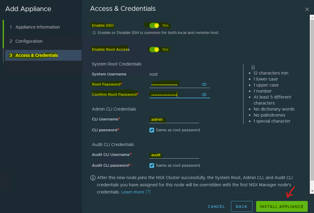
重复相同步骤以部署第三个 NSX 管理器节点。等待两个节点部署完成,并创建加入的集群。
为便于管理,分配集群 VIP。确保集群 IP 不会导致负载均衡。


NSX 管理器和控制器集群的部署已完成。
增强数据路径配置
网络管理员必须在创建启用增强数据路径模式的 VDS 传输区域之前,使用支持的网卡和驱动程序准备网络。
上行链路配置文件
上行链路配置文件定义了从虚拟机管理程序主机到 NSX 逻辑交换机的链路策略。
这些配置文件定义的设置可能包括成组策略、活动/备用链路、传输 VLAN ID 和 MTU 设置。
上行链路配置文件能够为跨多个主机和节点的网络适配器实现一致配置。默认情况下,NSX 提供两个上行链路配置文件,但由于它们无法编辑,因此应为边缘上行链路创建新的配置文件,同时也为主机上联创建配置文件。
有关详细信息,请参阅 创建上行链路配置文件。
创建主机上行链路配置文件
要创建主机上行链路配置文件,在 NSX Manager 中导航至 System → Fabric → Profiles → Uplink Profiles → +ADD。

- 为配置文件分配名称,并填写描述(可选)。
- 在 "Teamings" 下,将成组策略设置为 "Failover Order"。
- 将 Active Uplinks 设置为 uplink-1,将 Standby Uplinks 设置为 uplink-2。
Transport VLAN 将是一个 Overlay VLAN ID(在我们的示例中为 ")
- 1624), since these uplinks are connected directly to the hosts, and must be tagged accordingly.


Transport Zones
Transport Zones dictate which hosts (and consequently, which VMs) can participate in the use of a particular network. There are two types of transport zones - an Overlay and a VLAN.
- The overlay transport zone is used by both host transport nodes and NSX Edges, and is responsible for communication over the overlay network.
- The VLAN transport zone is used by the NSX Edge for its VLAN uplinks.
Both types create a VDS on the host or Edge to allow virtual-to-physical packet flow by binding logical router uplinks and downlinks to physical NICs. For more information, please see Transport Zones and Profiles.
Creating a Transport Zone
To create a Transport Zone in the NSX Manager, navigate to System → Fabric → Transport Zones → +ADD.

Transport Zone with Overlay Traffic Type
Provide a Name, and select the Traffic Type as Overlay (Geneve). Click ADD.


Traffic Type as VLAN is out of the scope of this document.
Creating an NSX IP Pool
Each transport node, i.e. hypervisors, is assigned with an IP address for the TEP interface. You can use DHCP, a Static IP list and an IP address Pool to assign IP addresses for the TEP (Tunnel Endpoint) interfaces. To configure the ESXi hosts as transport nodes, create an NSX IP Pool to assign IP addresses for the TEP interfaces.
To create an IP Pool in the NSX Manager:
-
Navigate to Networking → IP Address Pools → ADD IP ADDRESS POOL.

-
Specify the name and description of the IP address pool, and click "Set".

-
Click ADD SUBNET → Select "IP Ranges".

-
Specify the IP address ranges along with the CIDR and the Gateway IP address for the specified IP ranges. Click "ADD".

-
Click Apply.

-
Click "Save" to create the IP Pool.
 Once the IP Pool is created, the status is changed to "Success".
Host Transport Node
A host transport node is a node that participates in an NSX overlay or VLAN networking.
VDS Modes:
- Standard applies to all the supported hosts.
- Enhanced Datapath - Standard is an interrupt driven variant of the Enhanced Data Path mode.
- Enhanced Datapath - Performance is the Enhanced Data Path switch mode. This mode provides accelerated networking performance, but also introduces additional prerequisites. In order to benefit from this mode, workloads must be compiled with DPDK and use VMNET3 for their vNIC.
Installing NSX components on a Host Transport Node
To add a Host Transport Node:
- Ensure that at least one Physical NIC (pNIC) is available for NSX. In the below example, the host is configured with a ConnectX-6 Dx pNIC, vmnic0 on SL-WL01-Cluster.
- Make sure the ConnectX-6 Dx card is running firmware version 22.34.1002:
- Enable SSH Access to ESXi server.
- Log into ESXi vSphere Command-Line Interface with root permissions.
- Verify that
the host is equipped with an NVIDIA adapter card.
ESXi CLI
lspci | grep Mellanox
- Verify that driver firmware version 22.34.1002 is installed.
ESXi CLI
esxcli network nic get -n vmnic4
If the above driver versions are not installed, refer to the below user guides to learn how to upgrade your drivers to the latest versions: HowTo Install NVIDIA Firmware Tools (MFT) on VMware ESXi 6.7 and 7.0 - 解决方案 - NVIDIA Networking Docs
- Push out the necessary NSX components to the hosts.
In the NSX Manager, navigate to System → Fabric → Nodes → Host Transport Nodes, and from the "Managed By" dropdown menu, change the Managed by from Standalone Hosts to the vCenter server you just added.
By expanding the name of the cluster, you will be able to see that your hosts are not in a prepared state and are not connected to the NSX Controller.
Select the Cluster and click Configure NSX.

- Click on Create New Transport Node Profile.

- Provide the below details in the Add Transport Node Profile window
- Provide a profile Name (SL-WL01-TNP-EDP-STD).
- Select vCenter and VDS in the Name.
- From the Transport Zone dropdown menu, select the SL-WL01-Overlay-TZ - Overlay transport zone(s) created earlier.
- From the Uplink Profile dropdown menu, select the host uplink profile created earlier (Uplink-profile-01).
- From the IP Assignment dropdown menu, select the Use IP Pool.
- From the IP Pool dropdown menu, select the SL-WL01-TEP-IPpool Tunnel EndPoint (TEP) IP Pool created earlier.
- Select uplink-1 and uplink-2 in the Teaming Policy Uplink Mapping.
- From the Mode dropdown menu, select the Enhanced Datapath - Standard or Enhanced Datapath - Performance.

In case you selected the Enhanced Datapath - Performance mode, you must provide the CPU Config.
-
To provide the CPU Config, check to which NUMA node the NIC is connected:
-
Enable the SSH Access to ESXi server.
-
Log into ESXi vSphere Command-Line Interface with root permissions.
-
Run the following commands in ESXi CLI:
-
To find out the number for NUMA nodes on your host, run the "esxcli hardware memory get" command.
ESXi Host Console
~ esxcli hardware memory get Physical Memory: 274731274240 Bytes Reliable Memory: 0 Bytes NUMA Node Count: 4- To find out the NIC's affinity, run the following command:
vsish -e cat /net/pNics/<vmnicX>/properties | grep -i numaSample:
ESXi CLI
vsish -e cat /net/pNics/vmnic4/properties | grep -i numa
- Enter the CPU Config, select NUMA node and numbers of CPU Lcores.

-
Click ADD.
-
On the NSX Installation window, check a Transport Node Profile and click Apply.

This starts the host preparation process, so allow a few minutes for the NSX VIBs to be installed on the hosts and for the transport nodes to be configured.

In the vSphere cluster:

Click the refresh button as needed, until you see that the status is "Success" and that the status indicators are "Up".

In the vSphere Cluster:

验证 FPO Model 1 Level 1 已启用
以 root 权限登录 ESXi vSphere 命令行界面,并在 ESXi CLI 中运行以下命令以获取新 VDS 交换机和 VMK 接口的详细信息:
ESXi CLI
esxcfg-vswitch -l
ESXi CLI
esxcfg-vmknic -l
检查 VDS (SL-WL01-DS01) 上的 FPO 模型。
ESXi CLI
nsxdp-cli ens fpo get -dvs SL-WL01-DS01
检查 vmnic4(在我们的环境中)上的 FPO 模型。
ESXi CLI
nsxdp-cli ens fpo status get -n vmnic4
运行
nsxdp-cli命令查看 ENS 交换机。ESXi CLI
nsxdp-cli ens switch list
检查 ENS 端口。
要检查增强数据路径 - 性能模式(以前称为轮询模式)下的 ENS 端口,请运行以下命令:
ESXi CLI
nsxdp-cli ens port listESXi CLI
~ nsxdp-cli ens port list
portID      ensPID TxQ RxQ hwMAC             numMACs  type         Queue Placement(tx|rx)
------------------------------------------------------------------------------
67108883    0      1   1   00:50:56:6e:bc:a4 0        GENERIC      0 |0
67108884    1      1   1   00:50:56:62:ed:f9 0        GENERIC      0 |0
2214592526  2      1   2   00:00:00:00:00:00 0        UPLINK       0 |0
2214592533  2      1   2   00:00:00:00:00:00 0        UPLINK       0 |0
要检查增强数据路径 - 标准(以前称为中断模式)模式下的 ENS 端口,请运行以下命令:
ESXi CLI
nsxdp-cli ens port list
显示接口的 ENS 状态:确保 ENS driven 为 TRUE,并检查 Enhanced Datapath - Standard 模式在 vmnic4,5 上是否 Enabled/Disabled。
ESXi CLI
esxcfg-nics -e
确保 vmnic4,5 为 UP。
ESXi CLI
esxcfg-nics -l
创建 Segment
NSX Segment(以前称为逻辑交换机)是跨传输节点(ESXi 主机)的第 2 层连接表示,段之间具有第 3 层 IP 可达性。每个段分配有一个 VNI(虚拟网络标识符),类似于 VLAN ID。
连接到同一段的虚拟机可以相互通信,即使跨不同的物理主机通过 Geneve 隧道也是如此。
要创建 Segment:
-
从 NSX 管理器 UI 登录页面,使用 URL
https://<fqdn or IP>登录。 -
导航到 Networking → Segments。

-
点击 ADD Segment。

-
填写 Segment Name、Transport Zone、Subnets 和 VLAN。点击 SAVE。


-
Click NO.


-
If you enter your vCenter, and Navigate to Networking → VDS, you will now see this new Segment (Distributed Port Group) to which you can attach a VM.

Configuring a Virtual Machine
This section explains how to run DPDK TestPMD workload in the ENS Flow Processing Offload (FPO) Model 1 Level 1.
Warning: To configure the ENS Flow Processing Offload (FPO) Model 0, please see Appendix A.
Adding a 网卡 to a VM
-
Locate the Virtual Machine in the vSphere Web Client.
- Select a data center, folder, cluster, resource pool, or a host, and click the Related Objects tab.
- Click Virtual Machines, and select the virtual machine from the list.
-
Shut Down Host OS on the Virtual Machine. The VM is used with Ubuntu 20.04 Operation System.
-
For optimal performance and to attach the VM to the Segment created earlier, Select the VM, and go to "Edit Settings" → Virtual Hardware.

-
Click ADD NEW DEVICE → Network adapter.

-
Click on the NEW Network drop-down menu, and select Browse... Select the relevant Segment. In this case, the group is SL-WL01-EDP-Seg01. Click OK.

-
Expand the New Network section. Verify that the Adapter Type is VMXNET3, and change Shares to High.

-
For optimal performance, select logical processor affinity for this VM. To check the range of logical processors, run the following command.
ESXi CLI
vsish -e cat /hardware/cpuTopology/numa/nodes/0
-
Select the VM, right-click it, and select Edit Settings. Set Shares and Scheduling Affinity. Sample:

-
Select the VM Options tab. Expand the CPU Topology section.

-
Select Cores per Socket, NUMA Node and Device Assignment for New Network. Example:

-
Select Reserve all guest memory and set Memory Shares to High.

-
Enable Huge Page Support.
The virtual infrastructure supports backing Guest OS memory with 1GB Huge Pages for memory intensive and large memory DPDK applications.
To use 1GB Huge Pages to back the DPDK application's guest operating system memory, set sched.mem.lpage.enable1GPage = TRUE to the VM.
Error: Before you enable Huge Pages, consider the resource availability for other workloads in the cluster and for cluster operations such as HA and DRS.
To set Huge Pages, perform the following steps:
-
Click VM Options, and select Advanced.
-
Scroll down to Configuration Parameters, and select Edit Settings.
-
Click Add Configuration Params, and enter sched.mem.lpage.enable1GPage = TRUE. Click OK.

-
-
Power on the VM.
-
Set up a Static IP on the second VM's interface.

-
Check the ENS ports on the ESXi server.
ESXi CLI
nsxdp-cli ens port list
Error: Create a VM on the second ESXi host, and repeat the Add 网卡 to the VM step.
-
Run Ping.

-
Check the
Offload traffic running on the ESXi host:
ESXi CLI
[root@sl01w01esx12:~] nsxdp-cli ens flow-table dump -l 0
FT  dstMAC             srcMAC             VLAN  srcPort  srcIP                                          dstIP                                          proto  VNI      srcPort/type  dstPort/code  Actions hwHits               hwBytes
----------------------------------------------------------------------------------------------------------------------------------------------------------------------------------------------------------------------------------------------------
L4  00:50:56:9e:64:1a  00:50:56:9e:28:e7  0     3        192.168.121.122                                192.168.121.123                                1      66560    8             0              bmap:0x1400080 inval(s):131 cg:1091 dp:0x4 len:704; GENEVE DECAP; DFW on dstPort;   0  0

[root@sl01w01esx12:~] nsxdp-cli ens flow-table dump -l 1
FT  dstMAC             srcMAC             VLAN  srcPort  srcIP                                          dstIP                                          proto  VNI      srcPort/type  dstPort/code  Actions hwHits               hwBytes
----------------------------------------------------------------------------------------------------------------------------------------------------------------------------------------------------------------------------------------------------
L4  00:50:56:9e:28:e7  00:50:56:9e:64:1a  0     4        192.168.121.123                                192.168.121.122                                1      0        0             0              bmap:0x20000c0 inval(s):119 cg:1091 dp:0x3 len:814; DFW on srcPort; VNI: 66560; GENEVE ENCAP VNI: 66560;   0  0
Preparing the Driver for the DPDK Application
To prepare the driver for the DPDK, run the following steps in VM OS:
Build DPDK v20.05
-
Clone DPDK:
VM console
cd /root git clone git://dpdk.org/dpdk dpdk_repo cd dpdk_repo git checkout v20.05 -
Install meson:
VM console
apt install python3-pip sudo update-alternatives --install /usr/bin/python python /usr/bin/python3 1 pip3 install meson -
Install ninja:
VM console
cd /tmp wget https://github.com/ninja-build/ninja/releases/download/v1.10.2/ninja-linux.zip apt install unzip unzip ninja-linux.zip cp ninja /usr/local/bin/ -
Build DPDK:
VM console
cd /root/dpdk_repo meson -Dtests=false -Ddisable_drivers=net/ark,net/atlantic,net/avp,net/axgbe,net/bond,net/i*,net/p*,net/netvsc --prefix=`pwd`/dpdk-install build ninja -C build -
Prepare the Driver
Before the driver preparation, retrieve the second network interface name and ID.
To check the interface names, which are different from the management IP, follow this example:
VM console
~# ip a s
1: lo: <LOOPBACK,UP,LOWER_UP> mtu 65536 qdisc noqueue state UNKNOWN group default qlen 1000
link/loopback 00:00:00:00:00:00 brd 00:00:00:00:00:00
inet 127.0.0.1/8 scope host lo
valid_lft forever preferred_lft forever
inet6 ::1/128 scope host
valid_lft forever preferred_lft forever
2: ens160: <BROADCAST,MULTICAST,UP,LOWER_UP> mtu 1500 qdisc mq state UP group default qlen 1000
link/ether 00:50:56:bc:e3:6c brd ff:ff:ff:ff:ff:ff
inet 10.7.215.62/24 brd 10.7.215.255 scope global dynamic ens160
valid_lft 4602sec preferred_lft 4602sec
inet6 fe80::250:56ff:febc:e36c/64 scope link
valid_lft forever preferred_lft forever
3: ens192: <BROADCAST,MULTICAST,UP,LOWER_UP> mtu 1500 qdisc mq state UP group default qlen 1000
link/ether 00:50:56:bc:5b:10 brd ff:ff:ff:ff:ff:ff
inet 192.168.1.62/24 brd 192.168.1.255 scope global ens192
valid_lft forever preferred_lft forever
inet6 fe80::250:56ff:febc:5b10/64 scope link
valid_lft forever preferred_lft forever
In our case, ens192 is the second adapter.
Check the PCI ID of the driver.
Example:
VM console
~# lspci | grep VMXNET3
03:00.0 Ethernet controller: VMware VMXNET3 Ethernet Controller (rev 01)
0b:00.0 Ethernet controller: VMware VMXNET3 Ethernet Controller (rev 01)
In ours case it is 0b:00.0.
To prepare the driver, refer to the following example:
VM console
~# ifconfig ens192 0
~# /root/dpdk_repo/usertools/dpdk-devbind.py -u 0b:00.0
~# modprobe uio
~# insmod /root/dpdk-kmods/linux/igb_uio/igb_uio.ko
~# /root/dpdk_repo/usertools/dpdk-devbind.py -b igb_uio 0b:00.0
Verification
For verification, examine the network devices using the DPDK-compatible driver:
VM console
~# /root/dpdk_repo/usertools/dpdk-devbind.py --status-dev net

Network devices using DPDK-compatible driver
============================================
0000:0b:00.0 'VMXNET3 Ethernet Controller 07b0' drv=igb_uio unused=vmxnet3,vfio-pci

Network devices using kernel driver
===================================
0000:03:00.0 'VMXNET3 Ethernet Controller 07b0' if=ens160 drv=vmxnet3 unused=igb_uio,vfio-pci *Active*
Appendix A - Enable FPO Model 0
To Enable FPO Model 0, perform the following steps:
-
Check the FPO model.
-
Log into the ESXi vSphere Command-Line Interface with root permissions, and run the following commands in the ESXi CLI to view information about the new N-VDS switch and VMK interface(s).
ESXi CLI
esxcfg-vswitch -lESXi Host Console
esxcfg-vmknic -l
-
Check the FPO model on the VDS (SL-WL01-DS01) switch.
ESXi CLI
~ nsxdp-cli ens fpo get -dvs SL-WL01-DS01
-
Check the running FPO Model on the vmnic4 (in our environment).
ESXi Host Console
nsxdp-cli ens fpo status get -n vmnic4
-
-
...
RDG for VMware vSphere 8.0 with NSX 4.x Accelerated by NVIDIA Networking
Created on Dec 12 2022
Scope
This document provides details on the Enhanced Data Path (EDP) mode configuration on a VDS switch, using an NVIDIA network fabric
Enable FPO Model 0
-
Enable Model 0.
ESXi CLI
~ nsxdp-cli ens fpo set -dvs SL-WL01-DS01 --disable The new setting will take effect after reactivating ENS. -
Run the
nsxdp-clicommand to see the ENS switch.ESXi CLI
~ nsxdp-cli ens switch list name swID maxPorts numActivePorts numPorts mtu numLcores lcoreIDs ------------------------------------------------------------------------------ DvsPortset-0 0 16384 3 3 9000 1 0 -
Disable ENS by running the following command, and wait 5-10 seconds.
ESXi CLI
~ esxcfg-vswitch -Y DvsPortset-0 -
Enable the ENS.
To Enable ENS in the Enhanced Datapath - Performance mode (formerly - a Poll), run the following command.
ESXi Host Console
~ esxcfg-vswitch -y DvsPortset-0To Enable ENS in the Enhanced Datapath - Standard (formerly - an Interrupt) mode, please run the following command.
ESXi Host Console
~ esxcfg-vswitch -y -i DvsPortset-0 -
Check the FPO model.
ESXi CLI
~ nsxdp-cli ens fpo get -dvs SL-WL01-DS01 FPO is globally enabled. FPO is disabled on SL-WL01-DS01. FPO Model is set to Model 1 Level 1 but disabled on SL-WL01-DS01. Geneve Critical bit is enabled. IP Discovery through DHCP is enabled. IP Discovery through ICMP6 ND is disabled. -
Check the ENS ports.
To Check the ENS ports in the Enhanced Datapath - Standard (formerly - an Interrupt) mode, please run the following command.
ESXi CLI
~ nsxdp-cli ens port list portID ensPID TxQ RxQ hwMAC numMACs type Queue Placement(tx|rx) ------------------------------------------------------------------------------ 67108884 0 4 1 00:50:56:6c:57:41 0 VNIC 4 4 4 4 |5 67108885 1 4 1 00:50:56:63:0b:10 0 VNIC 2 2 2 2 |3 2214592528 2 24 24 04:3f:72:f5:92:6b 0 UPLINK 1 3 5 7 - - - - - - - - - - - - - - - - - - - - |0 0 0 0 0 2 4 6 - - - - - - - - - - - - - - - 2214592526 3 24 24 04:3f:72:f5:92:6a 0 UPLINK 1 3 5 7 - - - - - - - - - - - - - - - - - - - - |0 0 0 0 0 2 4 6 - - - - - - - - - - - - - - - -
Show ENS status of interfaces. ENS driven is TRUE on vmnic4 and vmnic5.
ESXi CLI
esxcfg-nics -e -
Check that
vmnic4andvmnic5is UP.ESXi CLI
esxcfg-nics -l -
Go to Configure a Virtual Machine steps.
Appendix B - Performance Testing
Performance Testing
Warning: Disclaimer: The performance results listed in this document are indicative, and should not be considered formal performance targets for NVIDIA products.
Setup

Setup Specs:
- Intel(R) Xeon(R) Gold 6130 CPU @ 2.10GHz, 16-Cores, 2 NUMA nodes
- RAM 96 GB
- NIC ConnectX-6 Dx dual-port (yet the traffic goes only to a single port with 100 Gb/s)
- Driver v4.23.0.36
- Firmware v22.34.1002
- VMware ESXi 8.0.0 build-20513097
- VMware vCenter 8.0.0 build-20920323
- VMware NSX 4.0.1.1.0.20598726
- DPDK & testpmd v21.05 with 5tswap forward-mode
- TRex v3.02 as a packet generator
Warning: The environment was optimized according to this document.
Commands
On the testpmd side:
In the test lab, 4 Cores are used for testpmd and 4 RX/TX queues.
VM console
# cd dpdk/build/app/
# ./dpdk-testpmd -l 0-5 --master-lcore=0 -w 0000:0b:00.0,rxq_cqe_comp_en=1,mprq_en=1,rxqs_min_mprq=1 --socket-mem=1024 --  --burst=64 --txd=2048 --rxd=2048 --mbcache=512 --rxq=4 --txq=4 --nb-cores=4 --forward-mode=5tswap -i -a --rss-udp --port-topology=loop
On the TRex side:
VM console
# cd v3.2/
# nohup ./t-rex-64 --no-scapy-server --no-ofed-check -i -c 8 &
# ./trex-console

> start -f udp_64_simple.py -m 2mpps -p 0
>tui
udp_64_simple.py file:
VM console
from trex_stl_lib.api import *

class STLS1(object):

    def create_stream (self):

        pkt = Ether()/IP(src="16.0.0.1",dst="48.0.0.1")/UDP(dport=12)/(22*'x')

        vm = STLScVmRaw( [
                                STLVmFlowVar(name="v_port",
                                                min_value=4337,
                                                  max_value=5337,
                                                  size=2, op="inc"),
                                STLVmWrFlowVar(fv_name="v_port",
                                            pkt_offset= "UDP.sport" ),
                                STLVmFixChecksumHw(l3_offset="IP",l4_offset="UDP",l4_type=CTRexVmInsFixHwCs.L4_TYPE_UDP),

                            ]
                        )

        return STLStream(packet = STLPktBuilder(pkt = pkt ,vm = vm ) ,
                                mode = STLTXCont(pps = 8000000) )

    def
get_streams (self, direction = 0, **kwargs): # create 1 stream return [ self.create_stream() ]
dynamic load - used for trex console or simulator
def register(): return STLS1()
Overlay Results

Conclusion
The benchmark results in this performance study show the great advantages of the Model 1 configuration in terms of MPPS.
Model 1 provides up to 16% performance improvement compared to Model 0.
The ConnectX-6 Dx network adapter allows to offload the entire data-path to the ConnectX hardware. This offloads the CPU from performing the data communication tasks and generates a significant performance boost that is critical in the new era of accelerated computing associated with a massive amount of data transfers.
Authors

Boris Kovalev
Boris Kovalev has worked for the past several years as a 解决方案 Architect, focusing on NVIDIA Networking/Mellanox technology, and is responsible for complex machine learning, Big Data and advanced VMware-based cloud research and design. Boris previously spent more than 20 years as a senior consultant and solutions architect at multiple companies, most recently at VMware. He has written multiple reference designs covering VMware, machine learning, Kubernetes, and container solutions which are available at the NVIDIA Documents website. - Specify the root password, and scroll down.