

Technology Preview for DPF deployment with NVIDIA DOCA SNAP service
Created on May 29, 2025 Scope This Technology Preview (TP) guide offers comprehensive instructions for deploying the NVIDIA DOCA SNAP service within a Kubernetes cluster using the DOCA Platform Framework. It details the step-by-step process for configuring the NVIDIA DOCA SNAP service over both TCP and RDMA transports on NVIDIA BlueField-3 DPU.
文档目录
Created on May 29, 2025
Scope
This Technology Preview (TP) guide offers comprehensive instructions for deploying the NVIDIA DOCA SNAP service within a Kubernetes cluster using the DOCA Platform Framework. It details the step-by-step process for configuring the NVIDIA DOCA SNAP service over both TCP and RDMA transports on NVIDIA BlueField-3 DPU.
This guide is designed for experienced system administrators, system engineers, and solution architects looking to provision Kubernetes pods with emulated PCIe block devices backed by networked storage. We will take full advantage of NVIDIA DPU hardware acceleration and offload capabilities, maximizing datacenter workload efficiency and performance.
Warning
- This reference implementation, as the name implies, is a specific, opiniated deployment example designed to address the usecase described above.
- While other approaches may exist to implement similar solutions, this document provides a detailed guide for this particular method.
Abbreviations and Acronyms
| Term | Definition | Term | Definition |
|---|---|---|---|
| BFB | BlueField Bootstream | OVN | Open Virtual Network |
| BGP | Border Gateway Protocol | PVC | Persistent Volume Claim |
| CNI | Container Network Interface | RDG | Reference Deployment Guide |
| CRD | Custom Resource Definition | RDMA | Remote Direct Memory Access |
| CSI | Container Storage Interface | SF | Scalable Function |
| DOCA | Data Center Infrastructure-on-a-Chip Architecture | SFC | Service Function Chaining |
| DOCA SNAP | NVIDIA® DOCA™ Storage-Defined Network Accelerated Processing | SPDK | Storage Performance Development Kit |
| DPF | DOCA Platform Framework | SR-IOV | Single Root Input/Output Virtualization |
| DPU | Data Processing Unit | TOR | Top of Rack |
| DTS | DOCA Telemetry Service | VF | Virtual Function |
| GENEVE | Generic Network Virtualization Encapsulation | VLAN | Virtual LAN (Local Area Network) |
| HBN | Host Based Networking | VRR | Virtual Router Redundancy |
| IPAM | IP Address Management | VTEP | Virtual Tunnel End Point |
| K8S | Kubernetes | VXLAN | Virtual Extensible LAN |
| MAAS | Metal as a Service |
Introduction
The NVIDIA BlueField-3 Data Processing Unit is a powerful infrastructure compute platform designed for high-speed processing of software-defined networking, storage, and cybersecurity. With a capacity of 400 Gb/s, BlueField-3 combines robust computing, high-speed networking, and extensive programmability to deliver hardware-accelerated, software-defined solutions for demanding workloads.
Deploying and managing DPU and their associated DOCA services, especially at scale, can be quite challenging. Without a proper provisioning and orchestration system, handling the DPU lifecycle and configuring DOCA services place a heavy operational burden on system administrators. The NVIDIA DOCA Platform Foundation addresses this challenge by streamlining and automating the lifecycle management of DOCA services.
NVIDIA DOCA unlocks the full potential of the BlueField platform, enabling rapid development of applications and services that offload, accelerate, and isolate data center workloads. One such example is NVIDIA DOCA SNAP, a DPU storage service that is designed to accelerate and optimize storage protocol by leveraging the capabilities of NVIDIA's BlueField DPU. NVIDIA DOCA SNAP technology encompasses a family of services that enable hardware-accelerated virtualization of local storage running on NVIDIA BlueField products. The SNAP services present networked storage as local block devices to the host, emulating local drives on the PCIe bus. At its core, DOCA SNAP enables high-performance, low-latency access to storage by allowing applications to interact directly with raw block devices - bypassing traditional filesystem overhead. As part of the DPF deployment model, the DOCA SNAP solution is composed of multiple functional components packaged into containers, which are deployed across both the x86 and DPU Kubernetes clusters.
This guide is similar to the RDG for DPF with OVN-Kubernetes and HBN Services document, which covers K8s cluster deployment with NVIDIA DOCA Host-Based Networking Service and OVN-Kubernetes CNI network plugin. In this guide, HBN enables the routing of OVN accelerated workload traffic together with storage protocol traffic on the server side by using BlueField as a BGP router.
This reference implementation leverages open-source components, and provides an end-to-end walkthrough of the deployment process, including:
- Infrastructure provisioning with MAAS
- Integration with NVIDIA’s DPF
- Deployment and orchestration of DPU-based services inside the Kubernetes cluster
- Configuration of BlueField devices with enabled NVMe emulation for DOCA SNAP service
- Management of DPU resources and workloads using Kubernetes-native constructs
This guide provides a comprehensive, practical example of installing the DPF system
在 Kubernetes 集群上使用 NVIDIA DOCA SNAP 服务,遵循 "存储开发指南"。
注意: 本指南中我们使用存储性能开发工具包 (SPDK) 作为存储后端服务的示例。此存储后端服务仅用于演示目的,不适用于生产用例,也不受支持。
参考资料
- NVIDIA BlueField DPU
- NVIDIA DOCA
- NVIDIA DOCA HBN 服务
- NVIDIA DOCA SNAP 服务
- NVIDIA DPF 发行说明
- NVIDIA DPF GitHub 仓库
- NVIDIA DPF 系统概述
- NVIDIA 以太网交换
- NVIDIA Cumulus Linux
- NVIDIA 网络算子
- 什么是 K8s?
- Kubespray
- OVN-Kubernetes
解决方案架构
关键组件和技术
-
NVIDIA BlueField® 数据处理单元 (DPU) NVIDIA® BlueField® 数据处理单元 (DPU) 为现代数据中心和超级计算集群带来了前所未有的创新。凭借其强大的计算能力和集成的软件定义硬件加速器(用于网络、存储和安全),BlueField 为任何环境中的任何工作负载创建了安全且加速的基础设施,开启了加速计算和人工智能的新时代。
-
NVIDIA DOCA 软件框架 NVIDIA DOCA™ 释放了 NVIDIA® BlueField® 网络平台的潜力。通过利用 BlueField DPU 和 SuperNIC 的强大功能,DOCA 能够快速创建卸载、加速和隔离数据中心工作负载的应用程序和服务。它使开发人员能够创建软件定义、云原生、DPU 和 SuperNIC 加速的服务,并具有零信任保护,满足现代数据中心的性能和安全需求。
-
NVIDIA ConnectX 智能网卡 10/25/40/50/100/200 和 400G 以太网网卡。业界领先的 NVIDIA® ConnectX® 智能网卡系列提供先进的硬件卸载和加速功能。NVIDIA 以太网网卡为超大规模、公有云和私有云、存储、机器学习、AI、大数据和电信平台提供了最高的投资回报率和最低的总拥有成本。
-
NVIDIA LinkX 线缆 NVIDIA® LinkX® 线缆和收发器产品系列提供了业界最完整的 10、25、40、50、100、200 和 400GbE 以太网以及 100、200 和 400Gb/s InfiniBand 产品线,适用于云、HPC、超大规模、企业、电信、存储和人工智能数据中心应用。
-
NVIDIA Spectrum 以太网交换机 灵活的外形,支持 16 到 128 个物理端口,速度从 1GbE 到 400GbE。基于针对性能和可扩展性优化的突破性硅技术,NVIDIA Spectrum 交换机非常适合构建高性能、高性价比、高效的云数据中心网络、以太网存储结构和深度学习互连。NVIDIA 将基于业界领先的专用集成电路 (ASIC) 技术的 NVIDIA Spectrum™ 交换机的优势与多种现代网络操作系统选择相结合,包括 NVIDIA Cumulus® Linux、SONiC 和 NVIDIA Onyx®。
-
NVIDIA Cumulus Linux NVIDIA® Cumulus® Linux 是业界最具创新性的开放网络操作系统,可让您像其他操作系统一样自动化、定制和扩展数据中心网络。
-
NVIDIA 网络算子 NVIDIA 网络算子简化了 Kubernetes 集群中 NVIDIA 网络资源的配置和管理。该算子自动安装所需的主机网络软件,汇集所有必要组件以提供高速网络连接。这些组件包括 NVIDIA 网络驱动程序、Kubernetes 设备插件、CNI 插件、IP 地址管理 (IPAM) 插件等。NVIDIA 网络算子与 NVIDIA GPU 算子协同工作,为可扩展的 GPU 计算集群提供高吞吐量、低延迟的网络。
-
Kubernetes Kubernetes 是一个开源容器编排平台,用于容器化应用程序的部署自动化、扩展和管理。
-
Kubespray Kubespray 是由 Ansible 剧本、清单、配置工具和领域知识组成的组合,用于通用操作系统/Kubernetes 集群配置管理任务,并提供:
- 高可用集群
- 可组合属性
- 支持大多数流行的 Linux 发行版
-
OVN-Kubernetes OVN-Kubernetes(开放虚拟网络 - Kubernetes)是一个开源项目,以 OVN(开放虚拟网络)和 Open vSwitch(开放虚拟交换机)为核心,为 Kubernetes 集群提供强大的网络解决方案。它是一个根据 CNI(容器网络接口)规范编写的 Kubernetes 网络合规插件。
-
RDMA RDMA 是一种允许网络中计算机在不涉及任一计算机的处理器、缓存或操作系统的情况下交换数据的技术。与本地 DMA 类似,RDMA 提高了吞吐量和性能,并释放了计算资源。
解决方案设计
解决方案逻辑设计
逻辑设计包括以下组件:
- 1 个 Hypervisor 节点(基于 KVM),配备 ConnectX-7
- 1 个防火墙虚拟机
- 1 个跳板虚拟机
- 1 个 MAAS 虚拟机
- 3 个虚拟机,运行主机/DPU 集群的所有 K8s 管理组件
- 2 个工作节点,每个节点配备 1 个 BlueField-3 网卡
- 存储目标节点,配备 ConnectX-7 和 SPDK 目标应用程序
- 单个 200 GbE 高速 (HS) 交换机
- 1 GbE 主机管理网络

SFC 逻辑图
DOCA 平台框架通过 K8s API 提供编排功能,简化了 DPU 管理。它负责 DPU 的配置和生命周期管理,编排专用 DPU 服务,并自动执行服务功能链 (SFC) 任务。这确保了 NVIDIA DOCA 服务和 OVN-Kubernetes CNI 的无缝部署,允许流量高效卸载并通过 HBN 数据平面路由。本指南中实现的 SFC 逻辑图如下所示。

磁盘模拟逻辑图
以下逻辑图展示了将磁盘挂载到租户工作负载 Pod 过程中涉及的主要组件。
收到新的模拟 NVMe 驱动器请求后,DOCA SNAP 组件通过 NVMe-oF 使用 RDMA 或 TCP 存储协议将块设备 (BDEV) 带到所需的 K8s 工作节点。然后,DPU 通过 "BlueField NVMe SNAP 控制器" 将其模拟为 x86 主机上的块设备。

防火墙设计
此解决方案中的 pfSense 防火墙具有双重用途:
- 防火墙 – 为 DPF 系统提供隔离环境,确保安全操作
- 路由器 – 实现互联网访问以及主机管理网络与高速网络之间的连接
SSH 和 RDP 的端口转发规则配置在防火墙上,用于将流量路由到主机管理网络中跳转节点的 IP 地址。从跳转节点,管理员可以管理和访问设置中的各种设备,以及处理 Kubernetes (K8s) 集群和 DPF 组件的部署。
下图说明了此解决方案中使用的防火墙设计:

软件栈组件

注意: 确保使用上述软件栈的完全相同版本。
物料清单

部署与配置
节点和交换机定义
以下是部署所演示网络结构时使用的定义和参数:
| 交换机端口使用 | ||
|---|---|---|
mgmt-switch | 1 | swp1-4 |
hs-switch | 1 | swp1,11-14,32 |
| 机架 | 服务器类型 | 服务器名称 | 交换机端口 | IP 和网卡 | 默认网关 |
|---|---|---|---|---|---|
| Rack1 | 虚拟机管理节点 | hypervisor | mgmt-switch: swp1hs-switch: swp1 | lab-br (接口 eno1): 可信 LAN IP mgmt-br (接口 eno2): - hs-br (接口 ens2f0np0): | 可信 LAN GW |
| Rack1 | 存储目标节点 | target | mgmt-switch: swp4hs-switch: swp32 | enp1s0f0: 10.0.110.25/24 enp144s0f0np0: 10.0.124.1/24 | 10.0.110.254 |
| Rack1 | 工作节点 | worker1 | mgmt-switch: swp2hs-switch: swp11-swp12 | ens15f0: 10.0.110.21/24 ens5f0np0/ens5f1np1: 10.0.120.0/22 | 10.0.110.254 |
| Rack1 | 工作节点 | worker2 | mgmt-switch: swp3hs-switch: swp13-swp14 | ens15f0: 10.0.110.22/24 ens5f0np0/ens5f1np1: 10.0.120.0/22 | 10.0.110.254 |
| Rack1 | 防火墙 (虚拟) | fw |
| Rack | Node Type | Hostname | DPU | Interface | Gateway |
|---|---|---|---|---|---|
| Rack1 | Firewall (Virtual) | pfsense | - | WAN (lab-br): Trusted LAN IP LAN (mgmt-br): 10.0.110.254/24 OPT1 (hs-br): 172.169.50.1/30 | Trusted LAN GW |
| Rack1 | Jump Node (Virtual) | jump | - | enp1s0: 10.0.110.253/24 | 10.0.110.254 |
| Rack1 | MAAS (Virtual) | maas | - | enp1s0: 10.0.110.252/24 | 10.0.110.254 |
| Rack1 | Master Node (Virtual) | master1 | - | enp1s0: 10.0.110.1/24 | 10.0.110.254 |
| Rack1 | Master Node (Virtual) | master2 | - | enp1s0: 10.0.110.2/24 | 10.0.110.254 |
| Rack1 | Master Node (Virtual) | master3 | - | enp1s0: 10.0.110.3/24 | 10.0.110.254 |
Wiring
Hypervisor Node
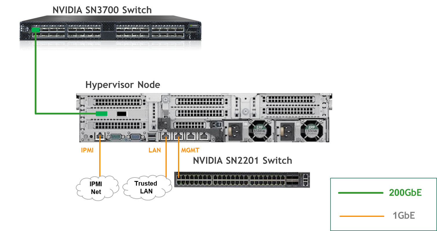
K8s Worker Node

Storage Target Node

Fabric Configuration
Updating Cumulus Linux
As a best practice, make sure to use the latest released Cumulus Linux NOS version.
For information on how to upgrade Cumulus Linux, refer to the Cumulus Linux User Guide.
Configuring the Cumulus Linux Switch
The SN3700 switch (hs-switch), is configured as follows:
Note:
- The following commands configure BGP unnumbered on
hs-switch.- Cumulus Linux enables the BGP equal-cost multipathing (ECMP) option by default.
SN3700 Switch Console
nv set bridge domain br_default vlan 10 vni 10
nv set evpn enable on
nv set interface lo ip address 11.0.0.101/32
nv set interface lo type loopback
nv set interface swp1 ip address 172.169.50.2/30
nv set interface swp1 link speed auto
nv set interface swp1-32 type swp
nv set interface swp32 bridge domain br_default access 10
nv set nve vxlan enable on
nv set nve vxlan source address 11.0.0.101
nv set qos roce enable on
nv set qos roce mode lossless
nv set router bgp autonomous-system 65001
nv set router bgp enable on
nv set router bgp graceful-restart mode full
nv set router bgp router-id 11.0.0.101
nv set system hostname hs-switch
nv set vrf default router bgp address-family ipv4-unicast enable on
nv set vrf default router bgp address-family ipv4-unicast redistribute connected enable on
nv set vrf default router bgp address-family ipv4-unicast redistribute static enable on
nv set vrf default router bgp address-family ipv6-unicast enable on
nv set vrf default router bgp address-family ipv6-unicast redistribute connected enable on
nv set vrf default router bgp address-family l2vpn-evpn enable on
nv set vrf default router bgp enable on
nv set vrf default router bgp neighbor swp11 peer-group hbn
nv set vrf default router bgp neighbor swp11 type unnumbered
nv set vrf default router bgp neighbor swp12 peer-group hbn
nv set vrf default router bgp neighbor swp12 type unnumbered
nv set vrf default router bgp neighbor swp13 peer-group hbn
nv set vrf default router bgp neighbor swp13 type unnumbered
nv set vrf default router bgp neighbor swp14 peer-group hbn
nv set vrf default router bgp neighbor swp14 type unnumbered
nv set vrf default router bgp path-selection multipath aspath-ignore on
nv set vrf default router bgp peer-group hbn address-family l2vpn-evpn enable on
nv set vrf default router bgp peer-group hbn remote-as external
nv set vrf default router static 0.0.0.0/0 address-family ipv4-unicast
nv set vrf default router static 0.0.0.0/0 via 172.169.50.1 type ipv4-address
nv set vrf default router static 10.0.110.0/24 address-family ipv4-unicast
nv set vrf default router static 10.0.110.0/24 via 172.169.50.1 type ipv4-address

nv config apply -y
The SN2201 switch (mgmt-switch) is configured as follows:
SN2201 Switch Console
nv set bridge domain br_default untagged 1
nv set interface swp1-4 link state up
nv set interface swp1-4 type swp
nv set interface swp1-4 bridge domain br_default
nv config apply -y
Host Configuration
Warning: Make sure that the BIOS settings on the worker node servers have SR-IOV enabled and that the servers are tuned for maximum performance.
Warning: All worker nodes must have the same PCIe placement for the BlueField-3 DPU and must show the same interface name.
Hypervisor Installation and Configuration
The hypervisor used in this guide is based on Ubuntu 24.04 with KVM.
While this document does not detail the KVM installation process, it is important to note that the setup requires the following ISOs to deploy the Firewall, Jump, and MAAS virtual machines (VMs):
- Ubuntu 24.04
- pfSense-CE-2.7.2
To implement the solution, three Linux bridges must be created on the hypervisor:
Caution: Ensure a DHCP record is configured for the
lab-brbridge interface in your trusted LAN to assign it an IP address.
lab-br– connects the Firewall VM to the trusted LAN.mgmt-br– Connects the various VMs to the host management network.hs-br– Connects the Firewall VM to the high-speed network.
Additionally, an MTU of 9000 must be configured on the management and high-speed bridges (mgmt-br and hs-br) as well
作为其上行接口,以确保最佳性能。
Hypervisor netplan 配置
network:
    ethernets:
        eno1:
            dhcp4: false
        eno2:
            dhcp4: false
            mtu: 9000
        ens2f0np0:
            dhcp4: false
            mtu: 9000
    bridges:
      lab-br:
         interfaces: [eno1]
         dhcp4: true
      mgmt-br:
         interfaces: [eno2]
         dhcp4: false
         mtu: 9000
      hs-br:
         interfaces: [ens2f0np0]
         dhcp4: false
         mtu: 9000
    version: 2
应用配置:
$ sudo netplan apply
准备基础设施服务器
防火墙虚拟机 - pfSense 安装与接口配置
下载 pfSense CE(社区版)ISO 到您的 hypervisor,并进行软件安装。
建议规格:
- vCPU:2
- RAM:2GB
- 存储:10GB
- 网络接口
- 连接到
lab-br的桥接设备 - 连接到
mgmt-br的桥接设备 - 连接到
hs-br的桥接设备
- 连接到
防火墙虚拟机必须连接到 hypervisor 上的所有三个 Linux 桥接。在开始安装之前,请确保配置了三个类型为 "Bridge device" 的虚拟网络接口。每个接口应连接到不同的桥接(lab-br、mgmt-br 和 hs-br),如下图所示。

安装完成后,设置向导会显示一个包含多个选项的菜单,例如 "Assign Interfaces" 和 "Reboot System"。在此阶段,您必须配置防火墙虚拟机的网络接口。
- 选择 Option 2: "Set interface(s) IP address" 并按如下方式配置接口:
- WAN (lab-br) – 受信任的 LAN IP(静态/DHCP)
- LAN (mgmt-br) – 静态 IP
10.0.110.254/24 - OPT1 (hs-br) – 静态 IP
172.169.50.1/30
- 接口配置完成后,使用主机管理网络内的 Web 浏览器访问防火墙 Web 界面并完成配置。
接下来,继续安装 Jump VM。该虚拟机将作为运行浏览器的平台,用于访问防火墙的 Web 界面进行安装后配置。
Jump VM
建议规格:
- vCPU:4
- RAM:8GB
- 存储:50GB
- 网络接口:桥接设备,连接到
mgmt-br
步骤:
-
进行标准的 Ubuntu 24.04 安装。在此设置中的所有主机上使用以下登录凭据:
用户名 密码 depuser user -
通过创建以下 Netplan 配置来启用互联网连接和 DNS 解析:
使用
10.0.110.254作为临时 DNS 名称服务器,直到 MAAS 虚拟机安装并配置完成。完成 MAAS 安装后,更新 Netplan 文件,将此地址替换为 MAAS IP:10.0.110.252。Jump Node netplan
network: ethernets: enp1s0: dhcp4: false addresses: [10.0.110.253/24] nameservers: search: [dpf.rdg.local.domain] addresses: [10.0.110.254] routes: - to: default via: 10.0.110.254 version: 2 -
应用配置:
depuser@jump:~$ sudo netplan apply -
更新并升级系统:
depuser@jump:~$ sudo apt update -y depuser@jump:~$ sudo apt upgrade -y -
安装并配置 Xfce 桌面环境 和 XRDP(RDP 的补充包):
depuser@jump:~$ sudo apt install -y xfce4 xfce4-goodies depuser@jump:~$ sudo apt install -y xrdp depuser@jump:~$ echo "xfce4-session" | tee .xsession depuser@jump:~$ sudo systemctl restart xrdp -
安装 Firefox 以访问防火墙 Web 界面:
$ sudo apt install -y firefox -
安装并配置 NFS 服务器,目录为
/mnt/dpf_share:$ sudo apt install -y nfs-server $ sudo mkdir -m 777 /mnt/dpf_share $ sudo vi /etc/exports -
将以下行添加到
/etc/exports:/mnt/dpf_share 10.0.110.0/24(rw,sync,no_subtree_check) -
重启 NFS 服务器:
$ sudo systemctl restart nfs-server -
在
/mnt/dpf_share下创建目录bfb,权限与父目录相同:$ sudo mkdir -m 777 /mnt/dpf_share/bfb -
在跳板节点上为
depuser生成 SSH 密钥对(稍后将导入 MAAS 管理员用户,以提供对已配置服务器的无密码登录):depuser@jump:~$ ssh-keygen -t rsa
防火墙虚拟机 – Web 配置
从您的跳板节点,打开 Firefox 浏览器并访问 pfSense Web UI(http://10.0.110.254,默认凭据为 admin/pfsense)。您应该会看到类似以下的页面:
受信任 LAN 网络下的 IP 地址("DNS servers" 和 "Interfaces - WAN")已模糊处理。

继续以下配置:
以下截图仅显示配置视图的一部分。请确保不要遗漏下面提到的任何步骤!
- 接口
- WAN – 勾选 "Enable interface",取消勾选 "Block private networks and loopback addresses"
- LAN – 勾选 "Enable interface","IPv4 configuration type":Static IPv4("IPv4 Address":10.0.110.254/24,"IPv4 Upstream Gateway":None),"MTU":9000
- OPT1 – 勾选 "Enable interface","IPv4
configuration type”: Static IPv4 ("IPv4 Address": 172.169.50.1/30, "IPv4 Upstream Gateway": None), “MTU”: 9000

-
Firewall:
-
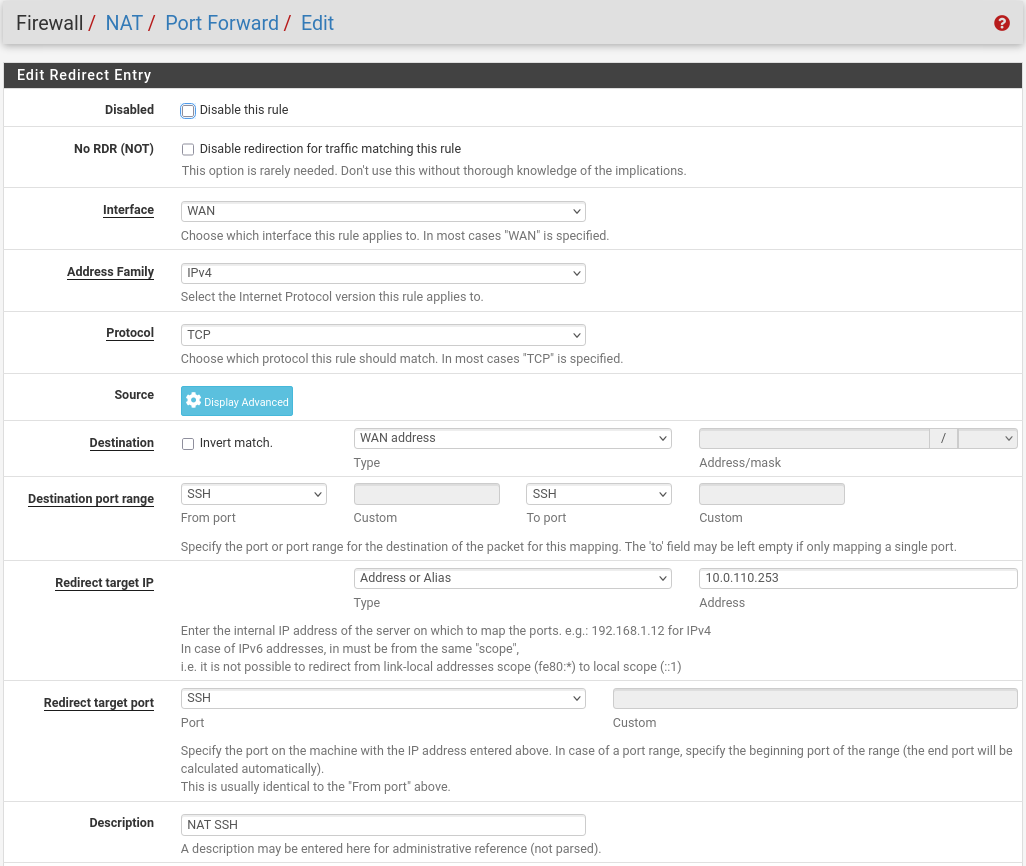
NAT -> Port Forward -> Add rule -> “Interface”: WAN, “Address Family”: IPv4, “Protocol”: TCP, “Destination”: WAN address, “Destination port range”: (“From port”: SSH, “To port”: SSH), “Redirect target IP”: (“Type”: Address or Alias, “Address”: 10.0.110.253), “Redirect target port”: SSH, “Description”: NAT SSH
-
NAT -> Port Forward -> Add rule -> “Interface”: WAN, “Address Family”: IPv4, “Protocol”: TCP, “Destination”: WAN address, “Destination port range”: (“From port”: MS RDP, “To port”: MS RDP), “Redirect target IP”: (“Type”: Address or Alias, “Address”: 10.0.110.253), “Redirect target port”: MS RDP, “Description”: NAT RDP

-
-
Rules -> OPT1 -> Add rule -> “Action”: Pass, “Interface”: OPT1, “Address Family”: IPv4+IPv6, “Protocol”: Any, “Source”: Any, “Destination”: Any

-
System:
-
Routing → Gateways → Add → “Interface”: OPT1, “Address Family”: IPv4, “Name”: switch, “Gateway”: 172.169.50.2 → Click "Save"→ Under "Default Gateway" - "Default gateway IPv4" choose WAN_DHCP → Click "Save"

Warning: Note that the IP addresses from the Trusted LAN network under "Gateway" and "Monitor IP" are blurred.

-
Routing → Static Routes → Add → “Destination network”: 10.0.120.0/22, “Gateway”: switch – 172.169.50.2, “Description”: To HS network → Click "Save"


-
MAAS VM
Suggested specifications:
- vCPU: 4
- RAM: 4GB
- Storage: 50GB
- Network interface: Bridge device, connected to
mgmt-br
Procedure:
-
Perform a regular Ubuntu installation on the MAAS VM.
-
Create the following Netplan configuration to enable internet connectivity and DNS resolution:
Warning: Use
10.0.110.254as a temporary DNS nameserver. After the MAAS installation, replace this with the MAAS IP address (10.0.110.252) in both the Jump and MAAS VM Netplan files.MaaS netplan
network: ethernets: enp1s0: dhcp4: false addresses: [10.0.110.252/24] nameservers: search: [dpf.rdg.local.domain] addresses: [10.0.110.254] routes: - to: default via: 10.0.110.254 version: 2 -
Apply the netplan configuration:
MaaS Console
depuser@maas:~$ sudo netplan apply -
Update and upgrade the system:
MaaS Console
depuser@maas:~$ sudo apt update -y depuser@maas:~$ sudo apt upgrade -y -
Install PostgreSQL and configure the database for MAAS:
MaaS Console
$ sudo -i # apt install -y postgresql # systemctl enable --now postgresql # systemctl disable --now systemd-timesyncd # export MAAS_DBUSER=maasuser # export MAAS_DBPASS=maaspass # export MAAS_DBNAME=maas # sudo -i -u postgres psql -c "CREATE USER \"$MAAS_DBUSER\" WITH ENCRYPTED PASSWORD '$MAAS_DBPASS'" # sudo -i -u postgres createdb -O "$MAAS_DBUSER" "$MAAS_DBNAME" -
Install MAAS:
MaaS Console
# snap install maas -
Initialize MAAS:
MaaS Console
# maas init region+rack --maas-url http://10.0.110.252:5240/MAAS --database-uri "postgres://$MAAS_DBUSER:$MAAS_DBPASS@localhost/$MAAS_DBNAME" -
Create an admin account:
MaaS Console
# maas createadmin --username admin --password admin --email admin@example.com -
Save the admin API key:
MaaS Console
# maas apikey --username admin > admin-apikey -
Log in to the MAA server:
MaaS Console
# maas login admin http://localhost:5240/MAAS "$(cat admin-apikey)" -
Configure MAAS (Substitute <Trusted_LAN_NTP_IP> and <Trusted_LAN_DNS_IP> with the IP addresses in your environment):
MaaS Console
# maas admin domain update maas name="dpf.rdg.local.domain" # maas admin maas set-config name=ntp_servers value="<Trusted_LAN_NTP_IP>" # maas admin maas set-config name=network_discovery value="disabled" # maas admin maas set-config name=upstream_dns value="<Trusted_LAN_DNS_IP>" # maas admin maas set-config name=dnssec_validation value="no" # maas admin maas set-config name=default_osystem value="ubuntu" -
Define and configure IP ranges and subnets:
MaaS Console
# maas admin ipranges create type=dynamic start_ip="10.0.110.51" end_ip="10.0.110.120"
# maas admin ipranges create type=dynamic start_ip="10.0.110.21" end_ip="10.0.110.30"
# maas admin ipranges create type=reserved start_ip="10.0.110.10" end_ip="10.0.110.10" comment="c-plane VIP"
# maas admin ipranges create type=reserved start_ip="10.0.110.200" end_ip="10.0.110.200" comment="kamaji VIP"
# maas admin ipranges create type=reserved start_ip="10.0.110.251" end_ip="10.0.110.254" comment="dpfmgmt"
# maas admin vlan update 0 untagged dhcp_on=True primary_rack=maas
# maas admin dnsresources create fqdn=kube-vip.dpf.rdg.local.domain ip_addresses=10.0.110.10
# maas admin dnsresources create fqdn=jump.dpf.rdg.local.domain ip_addresses=10.0.110.253
# maas admin dnsresources create
fqdn=fw.dpf.rdg.local.domain ip_addresses=10.0.110.254
maas admin fabrics create
Success. Machine-readable output follows: { "class_type": null, "name": "fabric-1", "id": 1, ...
maas admin subnets create name="fake-dpf" cidr="20.20.20.0/24" fabric=1
1. Complete MAAS setup:
1. Connect to the Jump node GUI and access the MAAS UI at `http://10.0.110.252:5240/MAAS`.
2. On the first page, verify the "Region Name" and "DNS Forwarder," then continue.
3. On the image selection page, select **Ubuntu 24.04 LTS (amd64)** and sync the image. 
4. Import the previously generated SSH key (`id_rsa.pub`) for the `depuser` into the MAAS admin user profile and finalize the setup. 
1. Configure DHCP snippets:
1. Navigate to **Settings → DHCP Snippets → Add Snippet**.
2. Fill in the following fields:
1. Name: `dpf-mgmt`
2. Toggle on "Enabled"
3. Type: IP Range
4. Applies to: `10.0.110.21`-`10.0.110.30`
3. Fill in the content of the DHCP snippet field with the following (replace MAC address as appropriate with your workers MGMT interface MAC):
**DHCP snippet**
```
# worker1
host worker1 {
#
# Node DHCP snippets
#
hardware ethernet 04:32:01:60:0d:da;
fixed-address 10.0.110.21;
}
# worker2
host worker2 {
#
# Node DHCP snippets
#
hardware ethernet 04:32:01:5f:cb:e0;
fixed-address 10.0.110.22;
}
# target
host target {
#
# Node DHCP snippets
#
hardware ethernet 0c:c4:7a:a4:b9:1c;
fixed-address 10.0.110.25;
}
```
1. Go to **Settings → Deploy**, set "Default OS release" to **Ubuntu 24.04 LTS Noble Numbat**, and save. 
1. Update the DNS nameserver IP address in both the Jump and MAAS VM Netplan files from `10.0.110.254` to `10.0.110.252` and reapply the configuration.
##### K8s Master VMs
Suggested specifications:
- vCPU: 8
- RAM: 16GB
- Storage: 100GB
- Network interface: Bridge device, connected to `mgmt-br`
1. Before provisioning the Kubernetes (K8s) Master VMs with MAAS, create the required virtual disks with empty storage. Use the following one-liner to create three 100 GB QCOW2 virtual disks:
**Hypervisor Console**
$ for i in $(seq 1 3); do qemu-img create -f qcow2 /var/lib/libvirt/images/master$i.qcow2 100G; done
This command generates the following disks in the `/var/lib/libvirt/images/` directory:
- `master1.qcow2`
- `master2.qcow2`
- `master3.qcow2`

1. Configure VMs in virt-manager:
1. Open **virt-manager** and create three virtual machines:
   - Assign the corresponding virtual disk (`master1.qcow2`, `master2.qcow2`, or `master3.qcow2`) to each VM.
   - Configure each VM with the suggested specifications (vCPU, RAM, storage, and network interface).
2. During the VM setup, ensure the **NIC** is selected under the **Boot Options** tab. This ensures the VMs can PXE boot for MAAS provisioning.
3. Once the configuration is complete, shut down all the VMs.

1. After the VMs are created and configured, proceed to provision them via the MAAS interface. MAAS will handle the OS installation and further setup as part of the deployment process.

#### Provision Master VMs, Workers and Storage Target Nodes Using MAAS

##### Master VMs

###### Install `virsh` and Set Up SSH Access

1. SSH to the MAAS VM from the Jump node:

**MaaS Console**
depuser@jump:$ ssh maas
depuser@maas:$ sudo -i
1. Install the `virsh` client to communicate with the hypervisor:

**MaaS Console**
apt install -y libvirt-clients
1. Generate an SSH key for the `root` user and copy it to the hypervisor user in the `libvirtd` group:

**MaaS Console**
ssh-keygen -t rsa
ssh-copy-id ubuntu@<hypervisor_MGMT_IP>
1. Verify SSH access and `virsh` communication with the hypervisor:

**MaaS Console**
virsh -c qemu+ssh://ubuntu@<hypervisor_MGMT_IP>/system list --all
Expected output:

**MaaS Console**
Id Name State
1    fw     running
2    jump   running
3    maas   running
-    master1       shut off
-    master2       shut off
-    master3       shut off
1. Copy the SSH key to the required MAAS directory (for snap-based installations):

**MaaS Console**
mkdir -p /var/snap/maas/current/root/.ssh
cp .ssh/id_rsa* /var/snap/maas/current/root/.ssh/
###### Get MAC Addresses of the Master VMs

Retrieve the MAC addresses of the Master VMs:

**MaaS Console**
for i in $(seq 1 3); do virsh -c qemu+ssh://ubuntu@<hypervisor_MGMT_IP>/system dumpxml master$i | grep 'mac address'; done
Example output:

**MaaS Console**
Add Master VMs to MAAS
-
Add the Master VMs to MAAS:
Once added, MAAS will automatically start commissioning the newly added VMs (discovery and introspection).
MaaS Console
# maas admin machines create hostname=master1 architecture=amd64/generic mac_addresses='52:54:00:a9:9c:ef' power_type=virsh power_parameters_power_address=qemu+ssh://ubuntu@<hypervisor_MGMT_IP>/system power_parameters_power_id=master1 skip_bmc_config=1 testing_scripts=none Success. Machine-readable output follows: { "description": "", "status_name": "Commissioning", ... "status": 1, ... "system_id": "c3seyq", ... "fqdn": "master1.dpf.rdg.local.domain", "power_type": "virsh", ... "status_message": "Commissioning", "resource_uri": "/MAAS/api/2.0/machines/c3seyq/" } # maas admin machines create hostname=master2 architecture=amd64/generic mac_addresses='52:54:00:19:6b:4d' power_type=virsh power_parameters_power_address=qemu+ssh://ubuntu@<hypervisor_MGMT_IP>/system power_parameters_power_id=master2 skip_bmc_config=1 testing_scripts=none # maas admin machines create hostname=master3 architecture=amd64/generic mac_addresses='52:54:00:68:39:7f' power_type=virsh power_parameters_power_address=qemu+ssh://ubuntu@<hypervisor_MGMT_IP>/system power_parameters_power_id=master3 skip_bmc_config=1 testing_scripts=none
Repeat the command for master2 and master3 with their respective MAC addresses.
Verify commissioning by waiting for the status to change to "Ready" in MAAS.

After commissioning, the next phase is the deployment (OS provisioning).
Configure OVS Bridges on Master VMs
To have persistency across reboots, create an OVS-bridge from each management interface of the master nodes and assign it a static IP address.
For each Master VM:
- Create an OVS bridge in the MAAS Network tab:
- Navigate to Network → Management Interface → Create Bridge.
- Configure as follows:
-
Name:
brenp1s0(prefixbradded to the interface name) -
Bridge Type: Open vSwitch (ovs)
-
Subnet: 10.0.110.0/24
-
IP Mode: Static Assign
-
Address: Assign
10.0.110.1formaster1,10.0.110.2formaster2, and10.0.110.3formaster3.
-
- Save the interface settings for each VM.
Deploy Master VMs Using Cloud-Init
-
Use the following cloud-init script to configure the necessary software and ensure OVS bridge persistency:
Warning: Replace
enp1s0andbrenp1s0in the following cloud-init with your interface names as displayed in MAAS network tab.Master nodes cloud-init
#cloud-config system_info: default_user: name: depuser passwd: "$6$jOKPZPHD9XbG72lJ$evCabLvy1GEZ5OR1Rrece3NhWpZ2CnS0E3fu5P1VcZgcRO37e4es9gmriyh14b8Jx8gmGwHAJxs3ZEjB0s0kn/" lock_passwd: false groups: [adm, audio, cdrom, dialout, dip, floppy, lxd, netdev, plugdev, sudo, video] sudo: ["ALL=(ALL) NOPASSWD:ALL"] shell: /bin/bash ssh_pwauth: True package_upgrade: true package_reboot_if_required: true package_update: true package_upgrade: true packages: - openvswitch-switch - nfs-common runcmd: - | UPLINK_MAC=$(cat /sys/class/net/enp1s0/address) ovs-vsctl set Bridge brenp1s0 other-config:hwaddr=$UPLINK_MAC ovs-vsctl br-set-external-id brenp1s0 bridge-id brenp1s0 -- br-set-external-id brenp1s0 bridge-uplink enp1s0 -
Deploy the Master VMs:
-
Select all three Master VMs → Actions → Deploy.
-
Toggle Cloud-init user-data and paste the cloud-init script.
-
Start the deployment and wait for the status to change to "Ubuntu 24.04 LTS".


-
Verify Deployment
-
SSH into the Master VMs from the Jump node:
Jump Node Console
depuser@jump:~$ ssh master1 depuser@master1:~$ -
Run
sudowithout password:Master1 Console
depuser@master1:~$ sudo -i root@master1:~# -
Verify installed packages:
Master1 Console
root@master1:~# apt list --installed | egrep 'openvswitch-switch|nfs-common' nfs-common/noble,now 1:2.6.4-3ubuntu5.1 amd64 [installed] openvswitch-switch/noble-updates,now 3.3.0-1ubuntu3.1 amd64 [installed] -
Check OVS bridge attributes:
Master1 Console
root@master1:~# ovs-vsctl list bridge brenp1s0Output example:
Master1 Console
...
external_ids        : {bridge-id=brenp1s0, bridge-uplink=enp1s0, netplan="true", "netplan/global/set-fail-mode"=standalone, "netplan/mcast_snooping_enable"="false", "netplan/rstp_enable"="false"}
...
other_config        : {hwaddr="52:54:00:a9:9c:ef"}
...
Finalize Setup
Reboot the Master VMs to complete the provisioning:
Master1 Console
root@master1:~# reboot
Worker and Storage Target Nodes
Create Workers and Target Machines in MAAS
-
Add the worker nodes to MAAS using
ipmias the power type. Replace placeholders with your specific IPMI credentials and IP addresses:Kernel options for worker nodes
# maas admin machines create hostname=worker1 architecture=amd64 power_type=ipmi power_parameters_power_driver=LAN_2_0 power_parameters_power_user=<IPMI_username_worker1> power_parameters_power_pass=<IPMI_password_worker1> power_parameters_power_address=<IPMI_address_worker1>Output example:
MaaS Console
... Success. Machine-readable output follows: { "description": "", "status_name": "Commissioning", ... "status": 1, ... "system_id": "pbskd3", ... "fqdn": "worker1.dpf.rdg.local.domain", ... "power_type": "ipmi", ... "resource_uri": "/MAAS/api/2.0/machines/pbskd3/" } -
Repeat the command for
worker2andtargetwith its respective credentials:Kernel options for worker nodes
# maas admin machines create hostname=worker2 architecture=amd64 power_type=ipmi power_parameters_power_driver=LAN_2_0 power_parameters_power_user=<IPMI_username_worker2> power_parameters_power_pass=<IPMI_password_worker2> power_parameters_power_address=<IPMI_address_worker2>
# maas admin machines create hostname=target architecture=amd64 power_type=ipmi power_parameters_power_driver=LAN_2_0 power_parameters_power_user=<IPMI_username_target> power_parameters_power_pass=<IPMI_password_target> power_parameters_power_address=<IPMI_address_target>
Once added, MAAS will automatically start commissioning the Worker and Storage Target nodes (discovery and introspection).
Adjust Network Settings
For each worker node, configure the network interfaces:
- Management Adapter:
- Go to Network → Select the host management adapter (e.g.,
ens15f0) → Create Bridge - Name:
br-dpu - Bridge Type: Standard
- Subnet:
10.0.110.0/24 - IP Mode: DHCP
- Save the interface
- Go to Network → Select the host management adapter (e.g.,
- BlueField Adapter:
- Select
P0on the BlueField adapter (e.g.,ens5f0np0) → Actions → Edit Physical - Fabric:
Fabric-1 - Subnet:
- Select
20.20.20.0/24 (fake-dpf)
- IP Mode: DHCP
- Save the interface
Repeat these steps for the second worker node.

For Storage Target Node, configure the network interfaces:
- Management Adapter:
- Go to Network → Select the host management adapter (e.g.,
ens1s0f0) → Edit Physical - Subnet:
10.0.110.0/24 - IP Mode: DHCP
- Save the interface
- Go to Network → Select the host management adapter (e.g.,
- ConnectX-7 Adapter:
- Leave unchanged
Deploy Worker Nodes Using Cloud-Init
-
Use the following cloud-init script for deployment:
Worker node cloud-init
#cloud-config system_info: default_user: name: depuser passwd: "$6$jOKPZPHD9XbG72lJ$evCabLvy1GEZ5OR1Rrece3NhWpZ2CnS0E3fu5P1VcZgcRO37e4es9gmriyh14b8Jx8gmGwHAJxs3ZEjB0s0kn/" lock_passwd: false groups: [adm, audio, cdrom, dialout, dip, floppy, lxd, netdev, plugdev, sudo, video] sudo: ["ALL=(ALL) NOPASSWD:ALL"] shell: /bin/bash ssh_pwauth: true package_reboot_if_required: true package_update: true package_upgrade: true packages: - nfs-common write_files: - path: /etc/sysctl.d/99-custom-netfilter.conf owner: root:root permissions: '0644' content: | net.bridge.bridge-nf-call-iptables=0 runcmd: - sysctl --system -
Deploy the worker nodes by selecting the worker nodes in MAAS → Actions → Deploy → Customize options → Enable Cloud-init user-data → Paste the cloud-init script → Deploy.
Deploy Storage Target Node Using Cloud-Init
-
Use the following cloud-init script for deployment:
Target node cloud-init
#cloud-config users: - default - name: depuser passwd: "$6$jOKPZPHD9XbG72lJ$evCabLvy1GEZ5OR1Rrece3NhWpZ2CnS0E3fu5P1VcZgcRO37e4es9gmriyh14b8Jx8gmGwHAJxs3ZEjB0s0kn/" lock_passwd: false groups: [adm, audio, cdrom, dialout, dip, floppy, lxd, netdev, plugdev, sudo, video] sudo: ["ALL=(ALL) NOPASSWD:ALL"] shell: /bin/bash ssh_pwauth: true package_reboot_if_required: true package_update: true package_upgrade: true packages: - nvme-cli -
Deploy the Storage Target Node by selecting the Storage Target Node in MAAS → Actions → Deploy → Customize options → Enable Cloud-init User-Data → Paste the cloud-init script → Deploy.
-
Manually assign an IP address to the DATA interface after node has been deployed in MAAS via netplan according to your SPDK IPAM CIDR (in our case 10.0.124.1/24)
Target node /etc/netplan/50-cloud-init.yaml
network:
  version: 2
  ethernets:
    # DATA interface
    enp144s0f0np0:
      match:
        macaddress: "04:3f:72:ed:97:d6"
      optional: true
      set-name: "enp144s0f0np0"
      mtu: 1500
      addresses:
      - "10.0.124.1/24"
      nameservers:
        addresses:
        - 10.0.110.252
        search:
        - dpf.rdg.local.domain
    enp144s0f1np1:
      match:
        macaddress: "04:3f:72:ed:97:d7"
      optional: true
      set-name: "enp144s0f1np1"
      mtu: 1500
    # Management interface
    enp1s0f0:
      match:
        macaddress: "0c:c4:7a:a4:b9:1c"
      dhcp4: true
      set-name: "enp1s0f0"
      mtu: 1500
    enp1s0f1:
      match:
        macaddress: "0c:c4:7a:a4:b9:1d"
      optional: true
      set-name: "enp1s0f1"
      mtu: 1500
Verify the Deployment
After the deployment is complete, verify that the worker nodes have been deployed successfully with the following commands:
-
SSH without password from the jump node:
Jump Node Console
depuser@jump:~$ ssh worker1 depuser@worker1:~$ -
Run
sudowithout password:Worker1 Console
depuser@worker1:~$ sudo -i root@worker1:~# -
Validate that the
nfs-commonpackage is installed:Worker1 Console
root@worker1:~# apt list --installed | grep 'nfs-common' nfs-common/noble,now 1:2.6.4-3ubuntu5.1 amd64 [installed] -
br_netfiltermodule is not loaded:Worker1 Console
root@worker1:~# lsmod | grep br_netfilter root@worker1:~# -
P0 interface has
dhcp4set totrueand does not havemtuline in thenetplanconfiguration file.Worker1 Console
root@worker1:~# cat /etc/netplan/50-cloud-init.yaml
network:
...
		ens5f0np0:
            dhcp4: true
            match:
                macaddress: a0:88:c2:46:78:c4
            set-name: ens5f0np0
...
Finalize Deployment
Reboot ALL nodes:
Jump Node Console
root@worker1:~# reboot
The infrastructure is now ready for the K8s deployment.
Provision SPDK Target Apps on Storage Target Node
-
Login as root account to Storage Target Node:
Jump Node Console
$ ssh target $ sudo -i -
Build SPDK from source (root privileges is required!):
Jump Node Console
git clone https://github.com/spdk/spdk cd spdk # v24.01 is the last version that is compatible with the spdk-csi git checkout v24.01 git submodule update --init apt update && apt install meson python3-pyelftools -y ./scripts/pkgdep.sh --rdma ./configure --with-rdma make -
Run SPDK target:
Jump Node Console
# Get all nvme devices lshw -c storage -businfo Bus info Device Class Description =========================================================== pci@0000:08:00.0 storage PCIe Data Center SSD pci@0000:00:11.4 storage C610/X99 series chipset sSATA Controller [AHCI mode] pci@0000:00:1f.2 storage C610/X99 series chipset 6-Port SATA Controller [AHCI mode] pci@0000:81:00.0 scsi4 storage MegaRAID SAS-3 3108 [Invader] # Start target scripts/setup.sh build/bin/nvmf_tgt & # Add bdevs with nvme backend scripts/rpc.py bdev_nvme_attach_controller -b Nvme0 -t PCIe -a 0000:08:00.0 # Add logical volume store on base bdev scripts/rpc.py bdev_lvol_create_lvstore Nvme0n1 lvs0 # Display current logical volume list scripts/rpc.py bdev_lvol_get_lvstores scripts/rpc_http_proxy.py 10.0.110.25 8000 exampleuser examplepassword & -
SPDK target is ready.
K8s Cluster Deployment and Configuration
Kubespray Deployment and Configuration
In this solution, the Kubernetes (K8s) cluster is deployed using a modified version of Kubespray (based on tag v2.26.0) with a non-root depuser account from the Jump Node. The modifications in Kubespray are designed to meet the DPF prerequisites, as described in the User Manual and to facilitate cluster deployment and scaling.
Download the modified Kubespray archive: modified_kubespray_v2.26.0.tar.gz.
-
Extract the contents and navigate to the extracted directory:
Jump Node Console
$ tar -xzf /home/depuser/modified_kubespray_v2.26.0.tar.gz $ cd kubespray/ depuser@jump:~/kubespray$ -
Set the K8s API VIP address and DNS record. Replace it with your own IP address and DNS record if different:
Jump Node Console
depuser@jump:~/kubespray$ sed -i '/ #kube_vip_address:/s/.*/kube_vip_address: 10.0.110.10/' inventory/mycluster/group_vars/k8s_cluster/addons.yml depuser@jump:~/kubespray$ sed -i '/apiserver_loadbalancer_domain_name:/s/.*/apiserver_loadbalancer_domain_name: "kube-vip.dpf.rdg.local.domain"/' roles/kubespray-defaults/defaults/main/main.yml -
Install the necessary dependencies and set up the Python virtual environment:
Jump Node Console
depuser@jump:~/kubespray$ sudo apt -y install python3-pip jq python3.12-venv depuser@jump:~/kubespray$ python3 -m venv .venv depuser@jump:~/kubespray$ source .venv/bin/activate (.venv) depuser@jump:~/kubespray$ python3 -m pip install --upgrade pip (.venv) depuser@jump:~/kubespray$ pip install -U -r requirements.txt (.venv) depuser@jump:~/kubespray$ pip install ruamel-yaml -
Review and edit the
inventory/mycluster/hosts.yamlfile to define the cluster nodes. The following is the configuration for this deployment:Warning:
- All of the nodes are already labeled and annotated as per the DPF User Manual prerequisites.
- The
kube_nodegroup is marked with#to deploy only the cluster with control plane nodes at the beginning. (Worker nodes will be added after the various components necessary for the DPF system are installed).
inventory/mycluster/hosts.yaml
all:
  hosts:
    master1:
      ansible_host: 10.0.110.1
      ip: 10.0.110.1
      access_ip: 10.0.110.1
      node_labels:
        "k8s.ovn.org/zone-name": "master1"
    master2:
      ansible_host: 10.0.110.2
      ip: 10.0.110.2
      access_ip: 10.0.110.2
      node_labels:
        "k8s.ovn.org/zone-name": "master2"
    master3:
      ansible_host: 10.0.110.3
      ip: 10.0.110.3
      access_ip: 10.0.110.3
      node_labels:
        "k8s.ovn.org/zone-name": "master3"
    worker1:
      ansible_host: 10.0.110.21
      ip: 10.0.110.21
      access_ip: 10.0.110.21
      node_labels:
        "node-role.kubernetes.io/worker": ""
        "k8s.ovn.org/dpu-host": ""
        "k8s.ovn.org/zone-name": "worker1"
      node_annotations:
        "k8s.ovn.org/remote-zone-migrated": "worker1"
    worker2:
      ansible_host: 10.0.110.22
      ip: 10.0.110.22
      access_ip: 10.0.110.22
      node_labels:
        "node-role.kubernetes.io/worker": ""
        "k8s.ovn.org/dpu-host": ""
        "k8s.ovn.org/zone-name": "worker2"
      node_annotations:
        "k8s.ovn.org/remote-zone-migrated": "worker2"
  children:
    kube_control_plane:
      hosts:
        master1:
        master2:
        master3:
    kube_node:
      hosts:
        worker1:
        worker2:
    etcd:
      hosts:
        master1:
        master2:
        master3:
    k8s_cluster:
      children:
        kube_control_plane:
#       kube_node:
Deploying Cluster Using Kubespray Ansible Playbook
-
Run the following command from the Jump Node to initiate deployment:
Warning: Ensure you are in the Python virtual environment (
.venv) when running the command.Jump Node Console
(.venv) depuser@jump:~/kubespray$ ansible-playbook -i inventory/mycluster/hosts.yaml --become --become-user=root cluster.yml -
It takes a while for this deployment to complete. Make sure there are no errors. A successful result example:

Tip: It is recommended to keep the shell from which Kubespray was running open; later on it will be useful when performing a cluster scale-out to add the worker nodes.
K8s Deployment Verification
To simplify managing the K8s cluster from the Jump Host, set up kubectl with bash auto-completion.
-
Copy
kubectland the kubeconfig file frommaster1to the Jump Host:Jump Node Console
## Connect to master1 depuser@jump:~$ ssh master1 depuser@master1:~$ cp /usr/local/bin/kubectl /tmp/ depuser@master1:~$ sudo cp /root/.kube/config /tmp/kube-config depuser@master1:~$ sudo chmod 644 /tmp/kube-config -
In another terminal tab, copy the files to the Jump Host:
Jump Node Console
depuser@jump:~$ scp master1:/tmp/kubectl /tmp/ depuser@jump:~$ sudo chown root:root /tmp/kubectl depuser@jump:~$ sudo mv /tmp/kubectl /usr/local/bin/ depuser@jump:~$ mkdir -p ~/.kube depuser@jump:~$ scp master1:/tmp/kube-config ~/.kube/config depuser@jump:~$ chmod 600 ~/.kube/config -
Enable bash auto-completion for
kubectl:-
Verify if bash-completion is installed:
Jump Node Console
depuser@jump:~$ type _init_completionIf installed, the output includes:
Jump Node Console
_init_completion is a function -
If bash-completion has not been installed, install it:
Jump Node Console
depuser@jump:~$ sudo apt install -y bash-completion -
Set up the
kubectlcompletion script:Jump Node Console
depuser@jump:~$ kubectl completion bash | sudo tee /etc/bash_completion.d/kubectl > /dev/null
depuser@jump:~$ bash
-
-
Check the status of the nodes in the cluster:
Jump Node Console
depuser@jump:~$ kubectl get nodesExpected output:
Warning: Nodes will be in the
NotReadystate because the deployment did not include CNI components.Jump Node Console
NAME STATUS ROLES AGE VERSION master1 NotReady control-plane 42m v1.30.4 master2 NotReady control-plane 41m v1.30.4 master3 NotReady control-plane 41m v1.30.4 -
Check the pods in all namespaces:
Jump Node Console
depuser@jump:~$ kubectl get pods -AExpected output:
Warning:
corednsanddns-autoscalerpods will be in thePendingstate due to the absence of CNI components.Jump Node Console
NAMESPACE     NAME                              READY   STATUS    RESTARTS   AGE
kube-system   coredns-776bb9db5d-ndr7j          0/1     Pending   0          41m
kube-system   dns-autoscaler-6ffb84bd6-xj9bv    0/1     Pending   0          41m
kube-system   kube-apiserver-master1            1/1     Running   0          43m
kube-system   kube-apiserver-master2            1/1     Running   0
DPF 安装
软件前提条件与所需变量
-
安装剩余的软件前提条件。
跳板机控制台
## 连接到 master1 以复制 kubespray 部署期间安装的 helm 客户端工具 $ depuser@jump:~$ ssh master1 depuser@master1:~$ cp /usr/local/bin/helm /tmp/ ## 在另一个标签页中 depuser@jump:~$ scp master1:/tmp/helm /tmp/ depuser@jump:~$ sudo chown root:root /tmp/helm depuser@jump:~$ sudo mv /tmp/helm /usr/local/bin/ ## 验证 envsubst 工具是否已安装 depuser@jump:~$ which envsubst /usr/bin/envsubst -
克隆 doca-platform Git 仓库(确保使用标签 v25.4.0):
跳板机控制台
$ git clone https://github.com/NVIDIA/doca-platform.git $ cd doca-platform $ git checkout v25.4.0 -
切换到 HBN-OVN 用例所在目录,后续所有命令均在此目录下运行:
跳板机控制台
$ cd docs/public/user-guides/hbn_ovn -
移除 HBN-OVN 部署用例中未使用的组件:
跳板机控制台
$ rm -rf manifests/05* manifests/06* -
下载本指南所需的 YAML 部署文件 hbn-ovn-snap.zip,然后解压:
跳板机控制台
$ unzip hbn-ovn-snap.zip $ ls -Ad manifests/* manifests/00-high-speed-switch-configuration manifests/01-cni-installation manifests/02-dpf-operator-installation manifests/03-dpf-system-installation manifests/04-enable-accelerated-cni manifests/05-dpudeployment-installation manifests/06-test-traffic -
使用 export_vars.env 文件定义安装所需的变量:
注意: 请将以下文件中的变量值替换为适合您环境的值。特别注意
DPU_P0、DPU_P0_VF1和DPUCLUSTER_INTERFACE。export_vars.env
## 目标集群(安装了 DPF)的 Kubernetes API 服务器 IP 地址。 ## 不应包含协议或端口。 ## 例如:10.10.10.10 export TARGETCLUSTER_API_SERVER_HOST=10.0.110.10 ## 目标集群(安装了 DPF)的 Kubernetes API 服务器端口。 export TARGETCLUSTER_API_SERVER_PORT=6443 ## 目标集群(安装了 DPF)中主机的 IP 地址范围。 ## 格式为 CIDR,例如 10.10.10.0/24 export TARGETCLUSTER_NODE_CIDR=10.0.110.0/24 ## DPU 集群负载均衡器使用的虚拟 IP。必须是管理子网中的保留 IP,且未被 DHCP 分配。 export DPUCLUSTER_VIP=10.0.110.200 ## DPU 的第一个端口名称。此名称在所有工作节点上必须相同。 export DPU_P0=ens5f0np0 ## DPU 第一个端口的第二个虚拟功能 (VF) 名称。此名称在所有工作节点上必须相同。 export DPU_P0_VF1=ens5f0v1 ## DPUCluster 负载均衡器将监听的接口。应为控制平面节点的管理接口。 export DPUCLUSTER_INTERFACE=brenp1s0 ## 用作 BFB 存储的 NFS 服务器 IP 地址。 export NFS_SERVER_IP=10.0.110.253 ## NVIDIA Helm 图表仓库的 URL。 ## 通常为 NVIDIA Helm NGC 仓库。开发用途可设置为其他仓库。 export NGC_HELM_REGISTRY_REPO_URL=https://helm.ngc.nvidia.com/nvidia/doca ## HBN 容器镜像的仓库 URL。 ## 通常为 NVIDIA NGC 仓库。开发用途可设置为其他仓库。 export HBN_NGC_IMAGE_URL=nvcr.io/nvidia/doca/doca_hbn ## OVN Kubernetes Helm 图表的仓库 URL。 ## 通常为 NVIDIA GHCR 仓库。开发用途可设置为其他仓库。 export OVN_KUBERNETES_REPO_URL=oci://ghcr.io/nvidia ## 目标 Kubernetes 集群中 Pod 使用的 CIDR。 export POD_CIDR=10.233.64.0/18 ## 目标 Kubernetes 集群中服务使用的 CIDR。 ## 格式为 CIDR,例如 10.10.10.0/24 export SERVICE_CIDR=10.233.0.0/18 ## DPF Operator 的 Helm 仓库 URL。 ## 通常为 GHCR 仓库。开发用途可设置为其他仓库。 export REGISTRY=https://helm.ngc.nvidia.com/nvidia/doca ## 本指南中部署的 DPF 组件版本。 export TAG=v25.4.0 ## `bfb.yaml` 中使用的 BFB URL,由 DPUSet 引用。 export BLUEFIELD_BITSTREAM="https://content.mellanox.com/BlueField/BFBs/Ubuntu22.04/bf-bundle-3.0.0-135_25.04_ubuntu-22.04_prod.bfb" -
导出安装所需的环境变量:
跳板机控制台
$ source export_vars.env
CNI 安装
OVN Kubernetes 用作集群的主 CNI。在工作节点上,主 CNI 将通过将工作卸载到 DPU 来加速。在控制平面节点上,OVN Kubernetes 将无卸载运行。
-
为 CNI 创建命名空间:
跳板机控制台
$ kubectl create ns ovn-kubernetes -
从 Helm 图表安装 OVN Kubernetes CNI 组件,并替换之前定义的环境变量。
commonManifests: enabled: true nodeWithoutDPUManifests: enabled: true controlPlaneManifests: enabled: true nodeWithDPUManifests: enabled: true nodeMgmtPortNetdev: $DPU_P0_VF1 dpuServiceAccountNamespace: dpf-operator-system gatewayOpts: --gateway-interface=$DPU_P0 ## 注意此 CIDR 后跟 /24,告知 OVN Kubernetes 如何按节点拆分 CIDR。 podNetwork: $POD_CIDR/24 serviceNetwork: $SERVICE_CIDR k8sAPIServer: https://$TARGETCLUSTER_API_SERVER_HOST:$TARGETCLUSTER_API_SERVER_PORT -
运行以下命令:
跳板机控制台
$ envsubst < manifests/01-cni-installation/helm-values/ovn-kubernetes.yml | helm upgrade --install -n ovn-kubernetes ovn-kubernetes ${OVN_KUBERNETES_REPO_URL}/ovn-kubernetes-chart --version $TAG --values - Release "ovn-kubernetes" does not exist. Installing it now. Pulled: ghcr.io/nvidia/ovn-kubernetes-chart:v25.4.0 Digest: sha256:bce61b35ab485f06924681c5c906bfc0ab0065ac94830c6c036418e1edf995b3 NAME: ovn-kubernetes LAST DEPLOYED: Tue May 20 08:51:29 2025 NAMESPACE: ovn-kubernetes STATUS: deployed REVISION: 1 TEST SUITE: None -
验证 CNI 安装:
注意: 以下验证命令可能需要多次运行以确保条件满足。
跳板机控制台
$ kubectl wait --for=condition=ready --namespace ovn-kubernetes pods --all --timeout=300s
pod/ovnkube-control-plane-7b9869d9bd-jd94x condition met
pod/ovnkube-node-2bpmd condition met
pod/ovnkube-node-d4mb8 condition met
pod/ovnkube-node-stxlv condition met

$ kubectl wait --for=condition=ready nodes --all
node/master1 condition met
node/master2 condition met
node/master3 condition met

$ kubectl wait --for=condition=ready --namespace kube-system pods --all
pod/coredns-776bb9db5d-ndr7j condition met
pod/coredns-776bb9db5d-w499z condition met
pod/dns-autoscaler-6ffb84bd6-xj9bv condition met
pod/kube-apiserver-master1 condition met
pod/kube-apiserver-master2 condition met
pod/kube-apiserver-master3 condition met
前提条件检查
验证所有控制平面 Pod 处于就绪状态:
pod/kube-controller-manager-master1 condition met
pod/kube-controller-manager-master2 condition met
pod/kube-controller-manager-master3 condition met
pod/kube-scheduler-master1 condition met
pod/kube-scheduler-master2 condition met
pod/kube-scheduler-master3 condition met
pod/kube-vip-master1 condition met
pod/kube-vip-master2 condition met
pod/kube-vip-master3 condition met
DPF Operator 安装
Cert-manager 安装
Cert-manager 是一个功能强大且可扩展的 X.509 证书控制器,适用于 Kubernetes 工作负载。它从各种签发者(包括流行的公共签发者和私有签发者)获取证书,确保证书有效且最新,并在配置的时间到期前尝试续订证书。
在此部署中,它是为 DPF 及其依赖项使用的 webhook 提供证书的先决条件。
-
为 Operator 创建命名空间:
跳板机控制台
$ kubectl create ns dpf-operator-system -
使用 Helm 安装 Cert-manager。
-
Helm chart 安装使用以下 values:
startupapicheck: enabled: false crds: enabled: true affinity: nodeAffinity: requiredDuringSchedulingIgnoredDuringExecution: nodeSelectorTerms: - matchExpressions: - key: node-role.kubernetes.io/master operator: Exists - matchExpressions: - key: node-role.kubernetes.io/control-plane operator: Exists tolerations: - operator: Exists effect: NoSchedule key: node-role.kubernetes.io/control-plane - operator: Exists effect: NoSchedule key: node-role.kubernetes.io/master cainjector: affinity: nodeAffinity: requiredDuringSchedulingIgnoredDuringExecution: nodeSelectorTerms: - matchExpressions: - key: node-role.kubernetes.io/master operator: Exists - matchExpressions: - key: node-role.kubernetes.io/control-plane operator: Exists tolerations: - operator: Exists effect: NoSchedule key: node-role.kubernetes.io/control-plane - operator: Exists effect: NoSchedule key: node-role.kubernetes.io/master webhook: affinity: nodeAffinity: requiredDuringSchedulingIgnoredDuringExecution: nodeSelectorTerms: - matchExpressions: - key: node-role.kubernetes.io/master operator: Exists - matchExpressions: - key: node-role.kubernetes.io/control-plane operator: Exists tolerations: - operator: Exists effect: NoSchedule key: node-role.kubernetes.io/control-plane - operator: Exists effect: NoSchedule key: node-role.kubernetes.io/master -
运行以下命令:
跳板机控制台
$ helm repo add jetstack https://charts.jetstack.io --force-update
$ helm upgrade --install --create-namespace --namespace cert-manager cert-manager jetstack/cert-manager --version v1.16.1 -f ./manifests/02-dpf-operator-installation/helm-values/cert-manager.yml

Release "cert-manager" does not exist. Installing it now.
NAME: cert-manager
LAST DEPLOYED: Tue May 20 12:59:30 2025
NAMESPACE: cert-manager
STATUS: deployed
REVISION: 1
TEST SUITE: None
NOTES:
cert-manager v1.16.1 has been deployed successfully!
-
-
验证 cert-manager 命名空间中的所有 Pod 均处于就绪状态:
跳板机控制台
$ kubectl wait --for=condition=ready --namespace cert-manager pods --all
pod/cert-manager-6ffdf6c5f8-tgv69 condition met
pod/cert-manager-cainjector-66b8577665-fbr5h condition met
pod/cert-manager-webhook-5cb94cb7b6-hb29q condition met
安装 CSI 以支持 DPUCluster etcd
-
将 local-path-provisioner Helm chart 下载到当前工作目录并为其创建命名空间:
跳板机控制台
$ curl https://codeload.github.com/rancher/local-path-provisioner/tar.gz/v0.0.30 | tar -xz --strip=3 local-path-provisioner-0.0.30/deploy/chart/local-path-provisioner/ $ kubectl create ns local-path-provisioner -
安装使用以下 values:
tolerations:
  - operator: Exists
    effect: NoSchedule
    key: node-role.kubernetes.io/control-plane
  - operator: Exists
    effect: NoSchedule
    key: node-role.kubernetes.io/master
运行以下命令:
跳板机控制台
$ helm install -n local-path-provisioner local-path-provisioner ./local-path-provisioner --version 0.0.30 -f ./manifests/02-dpf-operator-installation/helm-values/local-path-provisioner.yml NAME: local-path-provisioner LAST DEPLOYED: Tue May 20 13:01:40 2025 NAMESPACE: local-path-provisioner STATUS: deployed REVISION: 1 TEST SUITE: None NOTES: ... -
确保 local-path-provisioner 命名空间中的 Pod 处于就绪状态:
跳板机控制台
$ kubectl wait --for=condition=ready --namespace local-path-provisioner pods --all
pod/local-path-provisioner-75f649c47c-qb5w7 condition met
创建 DPF Operator 所需的存储
-
以下 YAML 文件定义了 DPF Operator 所需的存储(用于 BFB 镜像)。
--- apiVersion: v1 kind: PersistentVolume metadata: name: bfb-pv spec: capacity: storage: 10Gi volumeMode: Filesystem accessModes: - ReadWriteMany nfs: path: /mnt/dpf_share/bfb server: $NFS_SERVER_IP persistentVolumeReclaimPolicy: Delete --- apiVersion: v1 kind: PersistentVolumeClaim metadata: name: bfb-pvc namespace: dpf-operator-system spec: accessModes: - ReadWriteMany resources: requests: storage: 10Gi volumeMode: Filesystem -
运行以下命令,使用
envsubst替换环境变量并应用 YAML 文件:跳板机控制台
$ cat manifests/02-dpf-operator-installation/*.yaml | envsubst | kubectl apply -f -
DPF Operator 部署
-
DPF Operator Helm values 详见以下 YAML 文件:
kamaji-etcd:
  persistentVolumeClaim:
    storageClassName: local-path
node-feature-discovery:
  worker:
    extraEnvs:
      - name: "KUBERNETES_SERVICE_HOST"
        value: "$TARGETCLUSTER_API_SERVER_HOST"
      - name: "KUBERNETES_SERVICE_PORT"
        value: "$TARGETCLUSTER_API_SERVER_PORT"
运行以下命令替换环境变量并安装 DPF Operator:
跳板机控制台
$ helm repo add --force-update dpf-repository ${REGISTRY} $ helm repo update $ envsubst < ./manifests/02-dpf-operator-installation/helm-values/dpf-operator.yml | helm upgrade --install -n dpf-operator-system dpf-operator dpf-repository/dpf-operator --version=$TAG --values - Release "dpf-operator" does not exist. Installing it now. NAME: dpf-operator LAST DEPLOYED: Tue May 20 13:18:58 2025 NAMESPACE: dpf-operator-system STATUS: deployed REVISION: 1 TEST SUITE: None -
验证 DPF Operator 安装,确保部署可用且所有 Pod 处于就绪状态:
警告:以下验证命令可能需要多次运行以确保满足条件。
跳板机控制台
$ kubectl rollout status deployment --namespace dpf-operator-system dpf-operator-controller-manager
deployment "dpf-operator-controller-manager" successfully rolled out

$ kubectl wait --for=condition=ready --namespace dpf-operator-system pods --all
pod/dpf-operator-argocd-application-controller-0 condition met
pod/dpf-operator-argocd-applicationset-controller-84d86b665f-fqd6x condition met
pod/dpf-operator-argocd-redis-584fbbf667-zbhcb condition met
pod/dpf-operator-argocd-repo-server-6bff769f95-2cjgd condition met
pod/dpf-operator-argocd-server-54fcf54589-6cvqf condition met
pod/dpf-operator-controller-manager-54f76799c5-j4dcz condition met
pod/dpf-operator-kamaji-6dcf4ccdfd-lsgvd condition met
pod/dpf-operator-kamaji-etcd-0 condition met
pod/dpf-operator-kamaji-etcd-1 condition met
met pod/dpf-operator-kamaji-etcd-2 condition met pod/dpf-operator-maintenance-operator-7776bb95d-vnh5k condition met pod/dpf-operator-node-feature-discovery-gc-545bdbf8df-q68wp condition met pod/dpf-operator-node-feature-discovery-master-7df7dc844c-p64zz condition met
DPF System Installation
This section involves creating the DPF system components and some basic infrastructure required for a functioning DPF-enabled cluster.
-
The following YAML files define the DPFOperatorConfig to install the DPF System components. They also define the DPUCluster to serve as the Kubernetes control plane for the DPU nodes.
---
apiVersion: operator.dpu.nvidia.com/v1alpha1
kind: DPFOperatorConfig
metadata:
  name: dpfoperatorconfig
  namespace: dpf-operator-system
spec:
  overrides:
    kubernetesAPIServerVIP: $TARGETCLUSTER_API_SERVER_HOST
    kubernetesAPIServerPort: $TARGETCLUSTER_API_SERVER_PORT
  provisioningController:
    bfbPVCName: "bfb-pvc"
    dmsTimeout: 900
  kamajiClusterManager:
    disable: false
--- apiVersion: provisioning.dpu.nvidia.com/v1alpha1 kind: DPUCluster metadata: name: dpu-cplane-tenant1 namespace: dpu-cplane-tenant1 spec: type: kamaji maxNodes: 10 version: v1.30.2 clusterEndpoint: # deploy keepalived instances on the nodes that match the given nodeSelector. keepalived: # interface on which keepalived will listen. Should be the oob interface of the control plane node. interface: $DPUCLUSTER_INTERFACE # Virtual IP reserved for the DPU Cluster load balancer. Must not be allocatable by DHCP. vip: $DPUCLUSTER_VIP # virtualRouterID must be in range [1,255], make sure the given virtualRouterID does not duplicate with any existing keepalived process running on the host virtualRouterID: 126 nodeSelector: node-role.kubernetes.io/control-plane: "" -
Create namespace (NS) for the Kubernetes control plane of the DPU nodes:
Jump Node Console
$ kubectl create ns dpu-cplane-tenant1 -
Apply the previous YAML files:
Jump Node Console
$ cat manifests/03-dpf-system-installation/*.yaml | envsubst | kubectl apply -f - -
Verify the DPF system by ensuring that the provisioning and DPUService controller manager deployments are available. Also confirm that all other deployments in the DPF Operator system are available and that the DPUCluster is ready for nodes to join.
Jump Node Console
$ kubectl rollout status deployment --namespace dpf-operator-system dpf-provisioning-controller-manager dpuservice-controller-manager
deployment "dpf-provisioning-controller-manager" successfully rolled out
deployment "dpuservice-controller-manager" successfully rolled out

$ kubectl rollout status deployment --namespace dpf-operator-system
deployment "dpf-operator-argocd-applicationset-controller" successfully rolled out
deployment "dpf-operator-argocd-redis" successfully rolled out
deployment "dpf-operator-argocd-repo-server" successfully rolled out
deployment "dpf-operator-argocd-server" successfully rolled out
deployment "dpf-operator-controller-manager" successfully rolled out
deployment "dpf-operator-kamaji" successfully rolled out
deployment "dpf-operator-maintenance-operator" successfully rolled out
deployment "dpf-operator-node-feature-discovery-gc" successfully rolled out
deployment "dpf-operator-node-feature-discovery-master" successfully rolled out
deployment "dpf-provisioning-controller-manager" successfully rolled out
deployment "dpuservice-controller-manager" successfully rolled out
deployment "kamaji-cm-controller-manager" successfully rolled out

$ kubectl wait --for=condition=ready --namespace dpu-cplane-tenant1 dpucluster --all
dpucluster.provisioning.dpu.nvidia.com/dpu-cplane-tenant1 condition met
Install Components to Enable Accelerated CNI Nodes
OVN Kubernetes accelerates traffic by attaching a VF to each pod using the primary CNI. This VF offloads flows to the DPU, and this section details the components needed to connect pods to the offloaded OVN Kubernetes CNI.
Install Multus and SRIOV Network Operator using NVIDIA Network Operator
-
Add the NVIDIA Network Operator Helm repository:
Jump Node Console
$ helm repo add nvidia https://helm.ngc.nvidia.com/nvidia --force-update -
The following
network-operator.yamlvalues file will be applied:nfd: enabled: false deployNodeFeatureRules: false sriovNetworkOperator: enabled: true sriov-network-operator: operator: affinity: nodeAffinity: requiredDuringSchedulingIgnoredDuringExecution: nodeSelectorTerms: - matchExpressions: - key: node-role.kubernetes.io/master operator: Exists - matchExpressions: - key: node-role.kubernetes.io/control-plane operator: Exists crds: enabled: true sriovOperatorConfig: deploy: true configDaemonNodeSelector: null operator: affinity: nodeAffinity: requiredDuringSchedulingIgnoredDuringExecution: nodeSelectorTerms: - matchExpressions: - key: node-role.kubernetes.io/master operator: Exists - matchExpressions: - key: node-role.kubernetes.io/control-plane operator: ExistsDeploy the operator:
Jump Node Console
$ helm upgrade --no-hooks --install --create-namespace --namespace nvidia-network-operator network-operator nvidia/network-operator --version 24.7.0 -f ./manifests/04-enable-accelerated-cni/helm-values/network-operator.yml Release "network-operator" does not exist. Installing it now. NAME: network-operator LAST DEPLOYED: Tue May 20 13:36:57 2025 NAMESPACE: nvidia-network-operator STATUS: deployed REVISION: 1 TEST SUITE: None NOTES: ... -
Ensure all the pods in nvidia-network-operator namespace are ready:
Jump Node Console
$ kubectl wait --for=condition=ready --namespace nvidia-network-operator pods --all
pod/network-operator-7bc7b45d67-xk2fl condition met
pod/network-operator-sriov-network-operator-86c9cd4899-6hlzd condition met
Install OVN Kubernetes resource injection webhook
The OVN Kubernetes resource injection webhook is added to each pod scheduled to a worker node that requests a VF and a Network Attachment Definition. This webhook is part of the same helm chart as the other components of the OVN Kubernetes CNI. It is installed by modifying the existing helm deployment to include the webhook component.
-
The following
ovn-kubernetes.yamlvalues file will be applied:ovn-kubernetes-resource-injector: ## Enable the ovn-kubernetes-resource-injector enabled: true -
Run the following command:
Jump Node Console
$ envsubst < manifests/04-enable-accelerated-cni/helm-values/ovn-kubernetes.yml | helm upgrade --install -n ovn-kubernetes ovn-kubernetes-resource-injector ${OVN_KUBERNETES_REPO_URL}/ovn-kubernetes-chart --version $TAG --values - Release "ovn-kubernetes-resource-injector" does not exist. Installing it now. Pulled: ghcr.io/nvidia/ovn-kubernetes-chart:v25.4.0 Digest: sha256:bce61b35ab485f06924681c5c906bfc0ab0065ac94830c6c036418e1edf995b3 NAME: ovn-kubernetes-resource-injector LAST DEPLOYED: Tue May 20 13:41:38 2025 NAMESPACE: ovn-kubernetes STATUS: deployed REVISION: 1 TEST SUITE: None -
Verify that the resource injector deployment has been successfully rolled out.
Jump Node Console
$ kubectl rollout status deployment --namespace ovn-kubernetes ovn-kubernetes-ovn-kubernetes-resource-injector
deployment "ovn-kubernetes-ovn-kubernetes-resource-injector" successfully rolled out
Apply NicClusterPolicy and SriovNetworkNodePolicy
- Apply the following NicClusterPolicy and
SriovNetworkNodePolicy configuration files should be applied.
---
apiVersion: mellanox.com/v1alpha1
kind: NicClusterPolicy
metadata:
  name: nic-cluster-policy
spec:
  secondaryNetwork:
    multus:
      image: multus-cni
      imagePullSecrets: []
      repository: ghcr.io/k8snetworkplumbingwg
      version: v3.9.3
---
apiVersion: sriovnetwork.openshift.io/v1
kind: SriovNetworkNodePolicy
metadata:
  name: bf3-p0-vfs
  namespace: nvidia-network-operator
spec:
  mtu: 1500
  nicSelector:
    deviceID: "a2dc"
    vendor: "15b3"
    pfNames:
    - $DPU_P0#2-45
  nodeSelector:
    node-role.kubernetes.io/worker: ""
  numVfs: 46
  resourceName: bf3-p0-vfs
  isRdma: true
  externallyManaged: true
  deviceType: netdevice
  linkType: eth
Apply those configuration files:
Jump Node Console
$ cat manifests/04-enable-accelerated-cni/*.yaml | envsubst | kubectl apply -f -
Verify the DPF system by ensuring that the following DaemonSets were successfully rolled out:
Jump Node Console
$ kubectl rollout status daemonset --namespace nvidia-network-operator kube-multus-ds sriov-network-config-daemon sriov-device-plugin
daemon set "kube-multus-ds" successfully rolled out
daemon set "sriov-network-config-daemon" successfully rolled out
daemon set "sriov-device-plugin" successfully rolled out
DPU Provisioning and Service Installation
-
Provisioning limitations
Warning: The SPDK CSI image and helm chart are not provided as part of the DPF release. You need to build them following the instructions in dpuservices/storage/examples/spdk-csi/README.md. After building the image and chart, replace the placeholder values (such as
example.com/spdk-csi,oci://example.com, etc.) in the following SPDK CSI configuration examples with your actual repository locations and version information. -
Before deploying the objects under the
manifests/05-dpudeployment-installationdirectory, a few adjustments need to be made.-
Review
dpudeployment.yamlto reference the DPUFlavor suited for SNAP:--- apiVersion: svc.dpu.nvidia.com/v1alpha1 kind: DPUDeployment metadata: name: ovn-hbn-snap namespace: dpf-operator-system spec: dpus: bfb: bf-bundle flavor: dpf-provisioning-hbn-ovn-storage dpuSets: - nameSuffix: "dpuset1" nodeSelector: matchLabels: feature.node.kubernetes.io/dpu-enabled: "true" services: ovn: serviceTemplate: ovn serviceConfiguration: ovn hbn: serviceTemplate: hbn serviceConfiguration: hbn doca-snap: serviceTemplate: doca-snap serviceConfiguration: doca-snap snap-configuration: serviceTemplate: snap-configuration serviceConfiguration: snap-configuration snap-controller: serviceTemplate: snap-controller serviceConfiguration: snap-controller snap-csi-plugin: serviceTemplate: snap-csi-plugin serviceConfiguration: snap-csi-plugin snap-node-driver: serviceTemplate: snap-node-driver serviceConfiguration: snap-node-driver storage-vendor-dpu-plugin: serviceTemplate: storage-vendor-dpu-plugin serviceConfiguration: storage-vendor-dpu-plugin spdk-csi-controller: serviceTemplate: spdk-csi-controller serviceConfiguration: spdk-csi-controller spdk-csi-dpu-controller: serviceTemplate: spdk-csi-dpu-controller serviceConfiguration: spdk-csi-dpu-controller serviceChains: switches: - ports: - serviceInterface: matchLabels: uplink: p0 - service: name: hbn interface: p0_if - ports: - serviceInterface: matchLabels: uplink: p1 - service: name: hbn interface: p1_if - ports: - serviceInterface: matchLabels: port: ovn - service: name: hbn interface: pf2dpu2_if # SNAP interface - ports: - service: name: doca-snap interface: app_sf ipam: matchLabels: svc.dpu.nvidia.com/pool: spdk-pool - service: name: hbn interface: snap_if -
Set the
usernameandpasswordfor the spdk-target (as provided in SPDK apps installation):--- apiVersion: v1 kind: Secret metadata: name: spdkcsi-secret namespace: dpf-operator-system labels: # this label enables replication of the secret from the host to the dpu cluster dpu.nvidia.com/image-pull-secret: "" stringData: # name field in the "rpcTokens" list should match name of the # spdk target from DPUService.helmChart.values.host.config.targets.nodes secret.json: |- { "rpcTokens": [ { "name": "spdk-target", "username": "exampleuser", "password": "examplepassword" } ] } -
Set the
ipv4Subnetsettings for the spdk-pool (please note: GW IP should be assigned to DATA interface in Storage Target Node installation):--- apiVersion: svc.dpu.nvidia.com/v1alpha1 kind: DPUServiceIPAM metadata: name: pool1 namespace: dpf-operator-system spec: ipv4Network: network: "10.0.120.0/22" gatewayIndex: 3 prefixSize: 29 --- apiVersion: svc.dpu.nvidia.com/v1alpha1 kind: DPUServiceIPAM metadata: name: spdk-pool namespace: dpf-operator-system spec: metadata: labels: svc.dpu.nvidia.com/pool: spdk-pool ipv4Subnet: subnet: "10.0.124.0/24" gateway: "10.0.124.1" perNodeIPCount: 4 -
Set the
rpcURL,targetTypeandtargetAddrsettings according to your environment:--- apiVersion: svc.dpu.nvidia.com/v1alpha1 kind: DPUServiceConfiguration metadata: name: spdk-csi-controller namespace: dpf-operator-system spec: deploymentServiceName: "spdk-csi-controller" upgradePolicy: applyNodeEffect: false serviceConfiguration: deployInCluster: true helmChart: values: host: enabled: true plugin: image: # Shuold be replaced!!! repository: example.com/spdk-csi tag: v0.1.0 config: targets: nodes: # name of the target - name: spdk-target # management address rpcURL: http://10.0.110.25:8000 # type of the target, e.g. nvme-tcp, nvme-rdma targetType: nvme-rdma # target service IP targetAddr: 10.0.124.1 # required parameter, name of the secret that contains connection # details to access the DPU cluster. # this secret should be created by the DPUServiceCredentialRequest API. dpuClusterSecret: spdk-csi-controller-dpu-cluster-credentials -
The rest of the configuration files in the folder
manifest/05-dpudeployment-installation/remain the same, including:- BFB provisioning YAML: bfb.yaml
- DOCA-SNAP DPUService deployment and configuration YAMLs: dpuserviceconfig_doca-snap.yaml dpuservicetemplate_doca-snap.yaml
- HBN DPUService deployment and configuration YAMLs: dpuserviceconfig_hbn.yaml dpuservicetemplate_hbn.yaml
- OVN DPUService deployment and configuration YAMLs: dpuserviceconfig_ovn.yaml dpuservicetemplate_ovn.yaml
- SNAP configuration DPUService deployment and configuration YAMLs: dpuserviceconfig_snap-configuration.yaml dpuservicetemplate_snap-configuration.yaml
- SNAP controller DPUService deployment and configuration YAMLs: dpuserviceconfig_snap-controller.yaml dpuservicetemplate_snap-controller.yaml
- SNAP CSI plugin DPUService deployment and configuration YAMLs: dpuserviceconfig_snap-csi-plugin.yaml dpuservicetemplate_snap-csi-plugin.yaml
- SNAP node driver DPUService deployment and configuration YAMLs:
-
- SNAP node driver DPUService deployment and configuration YAMLs:
dpuserviceconfig_snap-node-driver.yamldpuservicetemplate_snap-node-driver.yaml
- SPDK CSI controller DPUService deployment and configuration YAMLs:
dpuserviceconfig_spdk-csi-controller.yamldpuservicetemplate_spdk-csi-controller.yaml
- SPDK CSI DPU controller DPUService deployment and configuration YAMLs:
dpuserviceconfig_spdk-csi-dpu-controller.yamldpuservicetemplate_spdk-csi-dpu-controller.yaml
- Storage vendor DPU plugin DPUService deployment and configuration YAMLs:
dpuserviceconfig_storage-vendor-dpu-plugin.yamldpuservicetemplate_storage-vendor-dpu-plugin.yaml
- DPUServiceIPAM for the loopback interface in HBN:
hbn-loopback-ipam.yaml
- OVN DPUServiceCredentialRequest to allow cross cluster communication:
ovn-credentials.yaml
- OVN DPUServiceInterface to define the ports attached to OVN workloads on the DPU:
ovn-iface.yaml
- DPUServiceInterfaces for physical ports on the DPU:
physical-ifaces.yaml
- SNAP DPUServiceCredentialRequest to allow cross cluster communication:
snap-credentials.yaml
-
Apply all of the YAML files mentioned above using the following command:
Jump Node Console
$ cat manifests/05-dpudeployment-installation/*.yaml | envsubst | kubectl apply -f - -
Verify the DPUService installation by ensuring the DPUServices are created and have been reconciled. Also verify that the DPUServiceIPAMs, DPUServiceInterfaces and DPUServiceChains have all been reconciled:
Notes
- These verification commands may need to be run multiple times to ensure the conditions are met.
- When using DPUDeployment, the DPUService name will have the DPUDeployment name added as prefix. For example,
ovn-hbn-hbn.
Jump Node Console
$ kubectl wait --for=condition=ApplicationsReconciled --namespace dpf-operator-system dpuservices --all
dpuservice.svc.dpu.nvidia.com/doca-snap-sk6hj condition met
dpuservice.svc.dpu.nvidia.com/flannel condition met
dpuservice.svc.dpu.nvidia.com/hbn-gjdzr condition met
dpuservice.svc.dpu.nvidia.com/multus condition met
dpuservice.svc.dpu.nvidia.com/nvidia-k8s-ipam condition met
dpuservice.svc.dpu.nvidia.com/ovn-tfc8q condition met
dpuservice.svc.dpu.nvidia.com/ovs-cni condition met
dpuservice.svc.dpu.nvidia.com/ovs-helper condition met
dpuservice.svc.dpu.nvidia.com/servicechainset-controller condition met
dpuservice.svc.dpu.nvidia.com/servicechainset-rbac-and-crds condition met
dpuservice.svc.dpu.nvidia.com/sfc-controller condition met
dpuservice.svc.dpu.nvidia.com/snap-configuration-48rqj condition met
dpuservice.svc.dpu.nvidia.com/snap-controller-vgvfl condition met
dpuservice.svc.dpu.nvidia.com/snap-csi-plugin-b76c4 condition met
dpuservice.svc.dpu.nvidia.com/snap-node-driver-ktx2c condition met
dpuservice.svc.dpu.nvidia.com/spdk-csi-controller-gmqcd condition met
dpuservice.svc.dpu.nvidia.com/spdk-csi-dpu-controller-v5sl5 condition met
dpuservice.svc.dpu.nvidia.com/sriov-device-plugin condition met
dpuservice.svc.dpu.nvidia.com/storage-vendor-dpu-plugin-8cksj condition met

$ kubectl wait --for=condition=DPUIPAMObjectReconciled --namespace dpf-operator-system dpuserviceipam --all
dpuserviceipam.svc.dpu.nvidia.com/loopback condition met
dpuserviceipam.svc.dpu.nvidia.com/pool1 condition met
dpuserviceipam.svc.dpu.nvidia.com/spdk-pool condition met

$ kubectl wait --for=condition=ServiceInterfaceSetReconciled --namespace dpf-operator-system dpuserviceinterface --all
dpuserviceinterface.svc.dpu.nvidia.com/doca-snap-app-sf-v8cfj condition met
dpuserviceinterface.svc.dpu.nvidia.com/hbn-p0-if-dg47c condition met
dpuserviceinterface.svc.dpu.nvidia.com/hbn-p1-if-t27cz condition met
dpuserviceinterface.svc.dpu.nvidia.com/hbn-pf2dpu2-if-w7w7l condition met
dpuserviceinterface.svc.dpu.nvidia.com/hbn-snap-if-6trz9 condition met
dpuserviceinterface.svc.dpu.nvidia.com/ovn condition met
dpuserviceinterface.svc.dpu.nvidia.com/p0 condition met
dpuserviceinterface.svc.dpu.nvidia.com/p1 condition met

$ kubectl wait --for=condition=ServiceChainSetReconciled --namespace dpf-operator-system dpuservicechain --all
dpuservicechain.svc.dpu.nvidia.com/ovn-hbn-snap-gj8f5 condition met
K8s Cluster Scale-out
Add Worker Nodes to the Cluster
At this point, workers should be added to the cluster. As they are added, DPU will be provisioned and DPUServices will begin to be spun up.
-
Return to the shell where Kubespray was previously run to deploy the cluster. Unmark the
kube_nodegroup in thehosts.yamlfile, and add the worker nodes to the cluster:Ensure you are in the Python virtual environment (
.venv) when running the command.Jump Node Console
(.venv) depuser@jump:~/kubespray$ cat inventory/mycluster/hosts.yaml ... k8s_cluster: children: kube_control_plane: kube_node: ... (.venv) depuser@jump:~/kubespray$ ansible-playbook -i inventory/mycluster/hosts.yaml --become --become-user=root scale.yml -
The scale-out shouldn't take a long time, and a successful run should look similar to the following output:

Verification
-
To follow the progress of the DPU provisioning, run the following command to check in which phase it currently is:
Jump Node Console
$ watch -n10 "kubectl describe dpu -n dpf-operator-system | grep 'Node Name\|Type\|Last\|Phase'" Every 10.0s: kubectl describe dpu -n dpf-operator-system | grep 'Node Name\|Type\|Last\|Phase' jump: Tue May 20 14:54:41 2025 Dpu Node Name: worker1 Last Transition Time: 2025-05-20T14:51:54Z Type: Initialized Last Transition Time: 2025-05-20T14:51:54Z Type: BFBReady Last Transition Time: 2025-05-20T14:52:09Z Type: NodeEffectReady Last Transition Time: 2025-05-20T14:52:10Z Type: InterfaceInitialized Last Transition Time: 2025-05-20T14:52:11Z Type: FWConfigured Phase: OS Installing Dpu Node Name: worker2 Last Transition Time: 2025-05-20T14:50:34Z Type: Initialized Last Transition Time: 2025-05-20T14:50:34Z Type: BFBReady Last Transition Time: 2025-05-20T14:50:49Z Type: NodeEffectReady Last Transition Time: 2025-05-20T14:50:50Z Type: InterfaceInitialized Last Transition Time: 2025-05-20T14:50:51Z Type: FWConfigured Phase: OS Installing -
Validate that the DPU have been provisioned successfully by ensuring they're in a ready state:
Jump Node Console
$ kubectl wait --for=condition=ready --namespace dpf-operator-system dpu --all dpu.provisioning.dpu.nvidia.com/worker1-0000-89-00 condition met dpu.provisioning.dpu.nvidia.com/worker2-0000-89-00 condition met -
Ensure that the following DaemonSets each have two ready replicas:
Jump Node Console
$ kubectl wait ds --for=jsonpath='{.status.numberReady}'=2 --namespace nvidia-network-operator kube-multus-ds sriov-network-config-daemon sriov-device-plugin daemonset.apps/kube-multus-ds condition met daemonset.apps/sriov-network-config-daemon condition met daemonset.apps/sriov-device-plugin condition met $ kubectl wait ds --for=jsonpath='{.status.numberReady}'=2 --namespace ovn-kubernetes ovnkube-node-dpu-host daemonset.apps/ovnkube-node-dpu-host condition met -
Validate that all the different DPUServices, DPUServiceIPAMs, DPUServiceInterfaces and DPUServiceChains objects are now in a ready state
Jump Node Console
$ kubectl wait --for=condition=ApplicationsReady --namespace dpf-operator-system dpuservices -l svc.dpu.nvidia.com/owned-by-dpudeployment=dpf-operator-system_ovn-hbn-snap
dpuservice.svc.dpu.nvidia.com/doca-snap-sk6hj condition met
dpuservice.svc.dpu.nvidia.com/hbn-gjdzr condition met
dpuservice.svc.dpu.nvidia.com/ovn-tfc8q condition met
dpuservice.svc.dpu.nvidia.com/snap-configuration-48rqj condition met
dpuservice.svc.dpu.nvidia.com/snap-controller-vgvfl condition met
dpuservice.svc.dpu.nvidia.com/snap-csi-plugin-b76c4 condition met
dpuservice.svc.dpu.nvidia.com/snap-node-driver-ktx2c condition met
dpuservice.svc.dpu.nvidia.com/spdk-csi-controller-gmqcd condition met
dpuservice.svc.dpu.nvidia.com/spdk-csi-dpu-controller-v5sl5 condition met
dpuservice.svc.dpu.nvidia.com/storage-vendor-dpu-plugin-8cksj condition met

$ kubectl wait --for=condition=DPUIPAMObjectReady --namespace dpf-operator-system dpuserviceipam --all
dpuserviceipam.svc.dpu.nvidia.com/loopback condition met
dpuserviceipam.svc.dpu.nvidia.com/pool1 condition met
dpuserviceipam.svc.dpu.nvidia.com/spdk-pool condition met

$ kubectl wait --for=condition=ServiceInterfaceSetReady --namespace dpf-operator-system dpuserviceinterface --all
dpuserviceinterface.svc.dpu.nvidia.com/doca-snap-app-sf-v8cfj condition met
dpuserviceinterface.svc.dpu.nvidia.com/hbn-p0-if-dg47c condition met
dpuserviceinterface.svc.dpu.nvidia.com/hbn-p1-if-t27cz condition met
dpuserviceinterface.svc.dpu.nvidia.com/hbn-pf2dpu2-if-w7w7l condition met
dpuserviceinterface.svc.dpu.nvidia.com/hbn-snap-if-6trz9 condition met
dpuserviceinterface.svc.dpu.nvidia.com/ovn condition met
dpuserviceinterface.svc.dpu.nvidia.com/p0 condition met
dpuserviceinterface.svc.dpu.nvidia.com/p1 condition met

$ kubectl wait --for=condition=ServiceChainSetReady --namespace dpf-operator-system dpuservicechain --all
dpuservicechain.svc.dpu.nvidia.com/ovn-hbn-snap-gj8f5 condition met
Congratulations, the DPF system has been successfully installed!
Deployment Validation
Warning The current implementation of DOCA SNAP for DPF supports only RAW Block device volumes.
To verify the DPF deployment with DOCA SNAP storage services by using following simple workload:
-
Deploy a simple workload pod with PVC storage provisioning:
manifests/06-test-traffic/snap-workloads.yaml
--- apiVersion: v1 kind: Pod metadata: name: snap-storage-pod spec: containers: - name: myfrontend image: ubuntu:24.04 command: - sh - -c - sleep inf volumeDevices: - name: data devicePath: /dev/xvda volumes: - name: data persistentVolumeClaim: claimName: myclaim --- apiVersion: v1 kind: PersistentVolumeClaim metadata: name: myclaim spec: storageClassName: snap accessModes: - ReadWriteOnce volumeMode: Block resources: requests: storage: 8Gi --- apiVersion: storage.k8s.io/v1 kind: StorageClass metadata: name: snap annotations: storageclass.kubernetes.io/is-default-class: "true" provisioner: csi.snap.nvidia.com parameters: policy: "policy1" -
Validate deployment with simple performance tests:
$ kubectl exec -it snap-storage-pod -- bash
root@snap-storage-pod:/# ls -la /dev/xvda
brw-rw---- 1 root disk 259, 8 May 27 09:31 /dev/xvda

root@snap-storage-pod:/# dd if=/dev/zero of=/dev/xvda bs=4k count=2000k
2048000+0 records in
2048000+0 records out
8388608000 bytes (8.4 GB, 7.8 GiB) copied, 2.42949 s, 3.5 GB/s
Create two job configuration files for FIO tests (FIO Ubuntu package should be installed:
apt-get install -y fio):root@snap-storage-pod:~# cat job-1M.fio [global] ioengine=libaio iodepth=32 direct=1 rw=read bs=1M numjobs=8 runtime=60 time_based group_reporting [job1] filename=/dev/xvda root@snap-storage-pod:~# cat job-4k.fio [global] ioengine=libaio direct=1 iodepth=32 rw=read bs=64k numjobs=8 runtime=60 time_based group_reporting [job1] filename=/dev/xvdaRun performance tests:
root@snap-storage-pod:~# fio job-1M.fio
job1: (g=0): rw=read, bs=(R) 1024KiB-1024KiB, (W) 1024KiB-1024KiB, (T) 1024KiB-1024KiB, ioengine=libaio, iodepth=32
...
fio-3.36
Starting 8 processes
Jobs: 8 (f=8): [R(8)][100.0%][r=3311MiB/s][r=3311 IOPS][eta 00m:00s]
job1: (groupid=0, jobs=8): err= 0: pid=3798: Tue May 27 09:33:41 2025
  read: IOPS=3236, BW=3237MiB/s (3394MB/s)(190GiB/60007msec)
    slat (usec): min=34, max=58507, avg=2469.73, stdev=7557.90
    clat (msec): min=5, max=161, avg=76.55, stdev=20.68
     lat (msec): min=5, max=163, avg=79.01, stdev=19.97
    clat percentiles (msec):
     |  1.00th=[   36],  5.00th=[   39], 10.00th=[   40], 20.00th=[   43],
     | 30.00th=[   84], 40.00th=[   86], 50.00th=[   87], 60.00th=[   88],
     | 70.00th=[   89], 80.00th=[   90], 90.00th=[   92], 95.00th=[   93],
     | 99.00th=[   96], 99.50th=[   99], 99.90th=[  107], 99.95th=[  114],
     | 99.99th=[  159]
   bw (  MiB/s): min= 2528, max= 3580, per=99.91%, avg=3233.68, stdev=16.98, samples=952
   iops        : min= 2524, max= 3580, avg=3233.56, stdev=17.00, samples=952
  lat (msec)   : 10=0.02%, 20=0.03%, 50=23.48%, 100=76.18%, 250=0.29%
  cpu          : usr=0.08%, sys=3.95%, ctx=1483542, majf=0, minf=203142
  IO depths    : 1=0.1%, 2=0.1%, 4=0.1%, 8=0.1%, 16=0.1%, 32=99.9%, >=64=0.0%
     submit    : 0=0.0%, 4=100.0%, 8=0.0%, 16=0.0%, 32=0.0%, 64=0.0%, >=64=0.0%
     complete  : 0=0.0%, 4=100.0%, 8=0.0%, 16=0.0%, 32=0.1%, 64=0.0%, >=64=0.0%
     issued rwts: total=194218,0,0,0 short=0,0,0,0 dropped=0,0,0,0
     latency   : target=0, window=0, percentile=100.00%, depth=32

Run status group 0 (all jobs):
   READ: bw=3237MiB/s (3394MB/s), 3237MiB/s-3237MiB/s (3394MB/s-3394MB/s), io=190GiB (204GB), run=60007-60007msec

Disk stats (read/write):
  nvme1n3: ios=1548902/0, sectors=396518912/0, merge=0/0, ticks=15298488/0, in_queue=15298488, util=99.90%

===================================================================================================================
root@snap-storage-pod:~# fio job-4k.fio
job1: (g=0): rw=read, bs=(R) 64.0KiB-64.0KiB, (W) 64.0KiB-64.0KiB, (T) 64.0KiB-64.0KiB, ioengine=libaio, iodepth=32
...
fio-3.36
Starting 8 processes
Jobs: 8 (f=8): [R(8)][100.0%][r=3193MiB/s][r=51.1k IOPS][eta 00m:00s]
job1: (groupid=0, jobs=8): err= 0: pid=3856: Tue May 27 09:35:22 2025
  read: IOPS=50.8k, BW=3175MiB/s (3329MB/s)(186GiB/60020msec)
    slat (usec): min=3, max=564, avg=10.33, stdev= 6.31
    clat (usec): min=1226, max=61859, avg=5028.10, stdev=10597.80
     lat (usec): min=1243, max=61869, avg=5038.44, stdev=10597.61
    clat percentiles (usec):
     |  1.00th=[ 1680],  5.00th=[ 1811], 10.00th=[ 1926], 20.00th=[ 2114],
     | 30.00th=[ 2278], 40.00th=[ 2409], 50.00th=[ 2540], 60.00th=[ 2671],
     | 70.00th=[ 2868], 80.00th=[ 3097], 90.00th=[ 3654], 95.00th=[45876],
     | 99.00th=[51643], 99.50th=[54264], 99.90th=[56361], 99.95th=[57934],
     | 99.99th=[58983]
   bw (  MiB/s): min= 2895, max= 3316, per=100.00%, avg=3177.29, stdev= 8.07, samples=952
   iops        : min=46332, max=53068, avg=50836.59, stdev=129.11, samples=952
  lat (msec)   : 2=14.08%, 4=78.17%, 10=2.71%, 20=0.01%, 50=1.51%
  lat (msec)   : 100=3.53%
  cpu          : usr=1.06%, sys=8.50%, ctx=2446739, majf=0, minf=4446
  IO depths    : 1=0.1%, 2=0.1%, 4=0.1%, 8=0.1%, 16=0.1%, 32=100.0%, >=64=0.0%
     submit    : 0=0.0%, 4=100.0%, 8=0.0%, 16=0.0%, 32=0.0%, 64=0.0%, >=64=0.0%
     complete  : 0=0.0%, 4=100.0%, 8=0.0%, 16=0.0%, 32=0.1%, 64=0.0%, >=64=0.0%
     issued rwts: total=3049161,0,0,0 short=0,0,0,0 dropped=0,0,0,0
     latency   : target=0, window=0, percentile=100.00%, depth=32

Run status group 0 (all jobs):
   READ: bw=3175MiB/s (3329MB/s), 3175MiB/s-3175MiB/s (3329MB/s-3329MB/s), io=186GiB (200GB), run=60020-60020msec

Disk stats (read/write):
  nvme1n3: ios=3043368/0, sectors=389554432/0, merge=26/0, ticks=15279103/0, in_queue=15279103, util=99.86%
At the end of the test, you'll see the achieved performance.
Warning The performance results listed in this guide are indicative and should not be considered as formal performance targets for NVIDIA products.
Authors
 | Vitaliy Razinkov Vitaliy Razinkov is a 解决方案 Architect on the NVIDIA Networking team, specializing in complex Kubernetes, OpenShift, and Microsoft solutions. With over 25 years of experience in senior technical roles, he brings deep expertise in designing and implementing advanced infrastructures. Vitaliy has authored several reference design guides on Microsoft technologies, RoCE/RDMA-accelerated machine learning in Kubernetes/OpenShift, and containerized solutions—all available on the NVIDIA Networking 文档 site. |